Device for coupling clothing hangers together and providing a comfortable grip for carrying

a technology of clothing hangers and hooks, which is applied in the field of cloth hangers, can solve the problems of difficult control of devices, garment slippage off hangers, uncomfortable pressure of hanger hooks, etc., and achieve the effect of comfortable hand grip

Inactive Publication Date: 2008-11-06
NEHER GEORGE
View PDF22 Cites 2 Cited by
  • Summary
  • Abstract
  • Description
  • Claims
  • Application Information

AI Technical Summary

Benefits of technology

[0017]This device provides for coupling multiple clothes hangers together and for and for providing a comfortable hand grip. The device includes multiple clothes hangers with each of the hangers having an attachment section and a clothes section. The attachment section has an outside end and

Problems solved by technology

The pressure of the hanger hooks is uncomfortable and garments slip off the hangers and are hard to control.
The difficulties of multiple hangers pertains to hangers both outside of a garment bag and inside a garment bag except that inside a garment bag, the clothes are retained and do not fall on the ground.
The device is comparatively complex and provision for a cushioned grip is not included.

Method used


Image

  • Device for coupling clothing hangers together and providing a comfortable grip for carrying
  • Device for coupling clothing hangers together and providing a comfortable grip for carrying
  • Device for coupling clothing hangers together and providing a comfortable grip for carrying

Examples


first embodiment

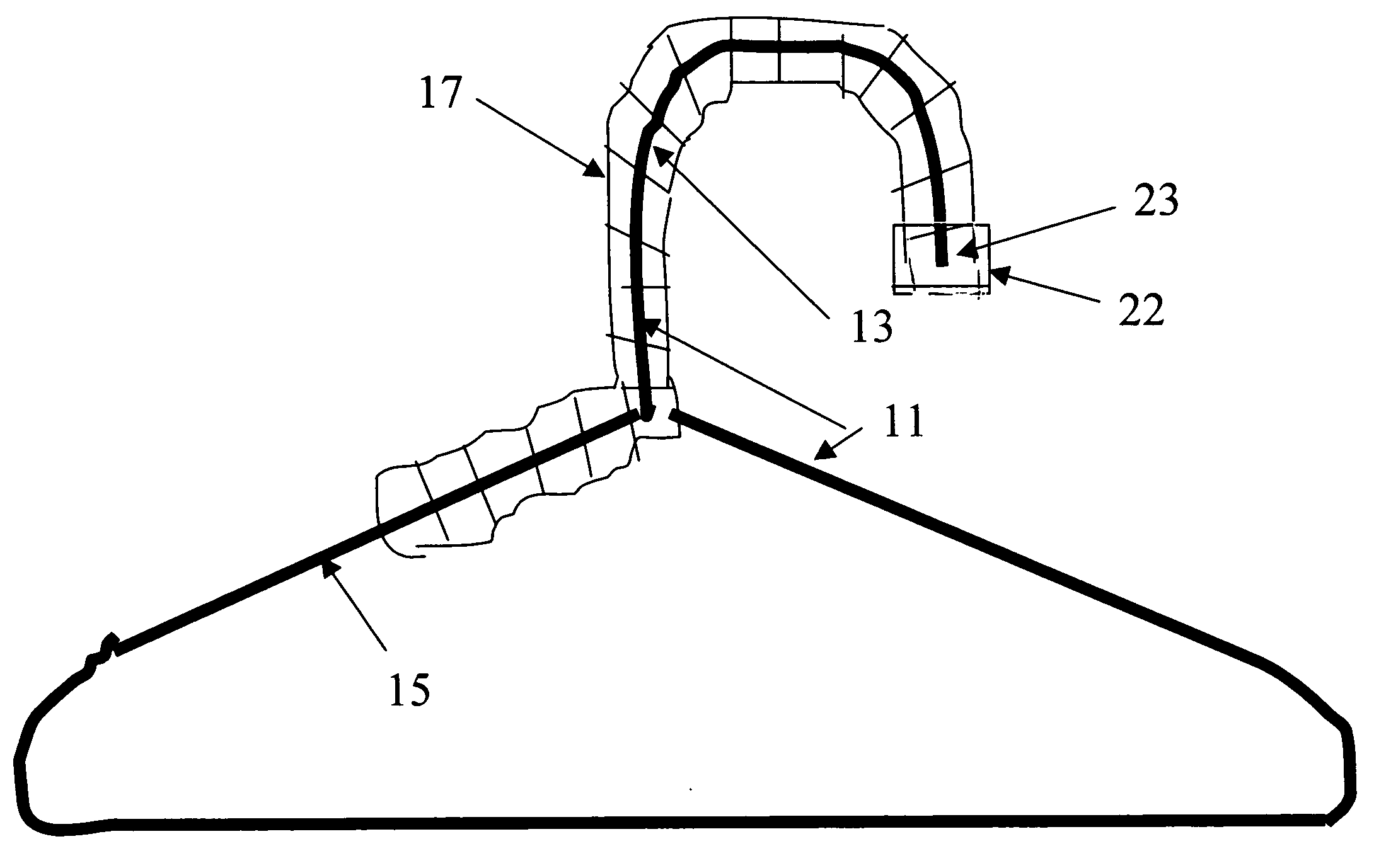
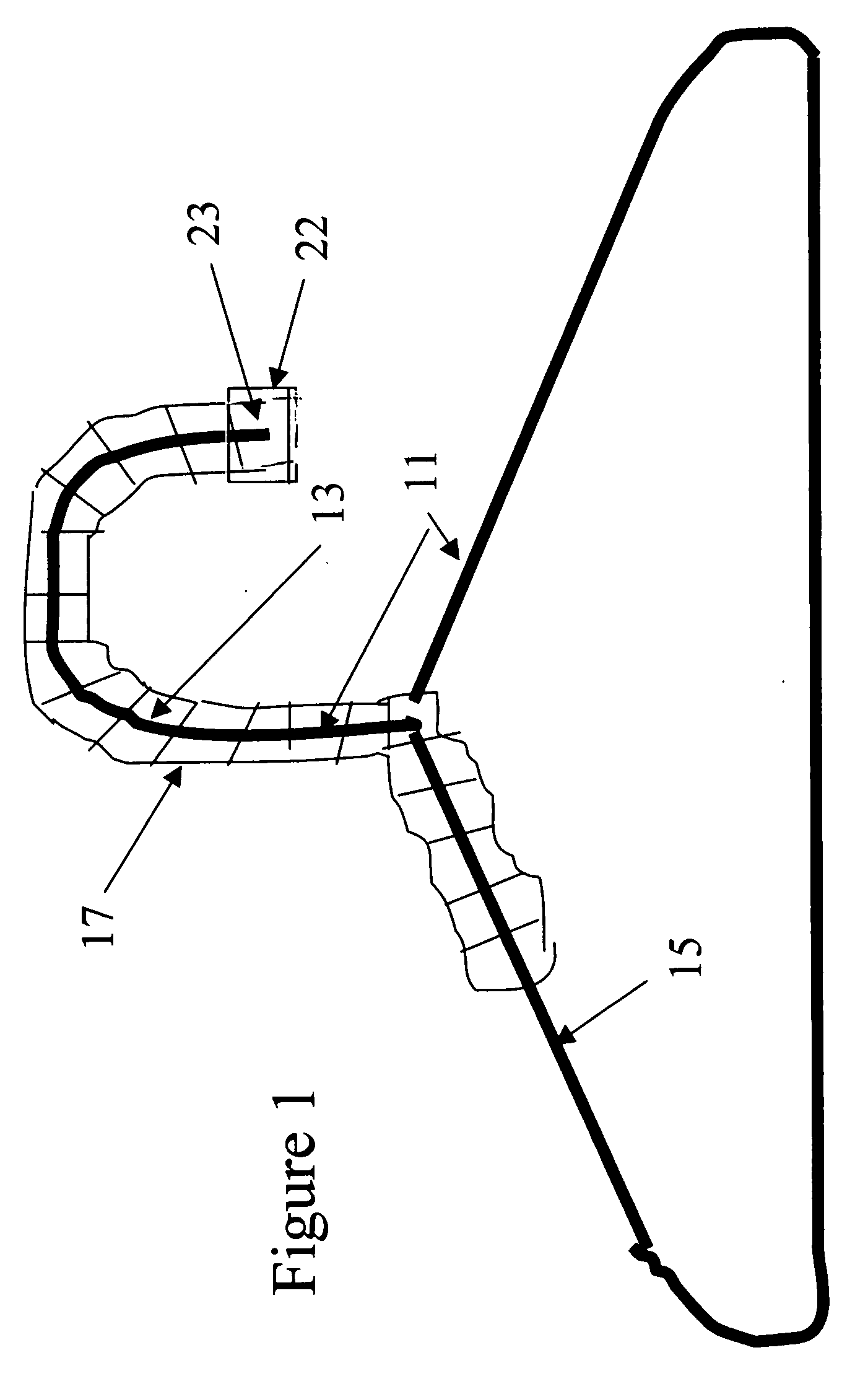
[0026]FIGS. 1, 2 and 3 depict the invention which utilizes hook and loop material 17WH which is preferably padded. The clothes hangers are standard metal or standard plastic hangers. The hook and loop material 17 is two sided (FIG. 3) with hooks 19 on one side and loops 21 on the opposite side. In this way, as the hook and loop material 17 is wrapped about the attachment section 13, it secures itself to the hanger. Hook and loop material 17, as is known, also secures to itself and is retained on the upper section 13 of the hangers. The hook and loop material 17 createds a soft padding for comfortable gripping.

[0027]A cap 21 is forced over the open ends 23 of the attachment sections 13 of a group of hangers. The cap 21 makes the open ends 23 of the group of hangers blunt so as not to injure anyone gripping the group of hangers.

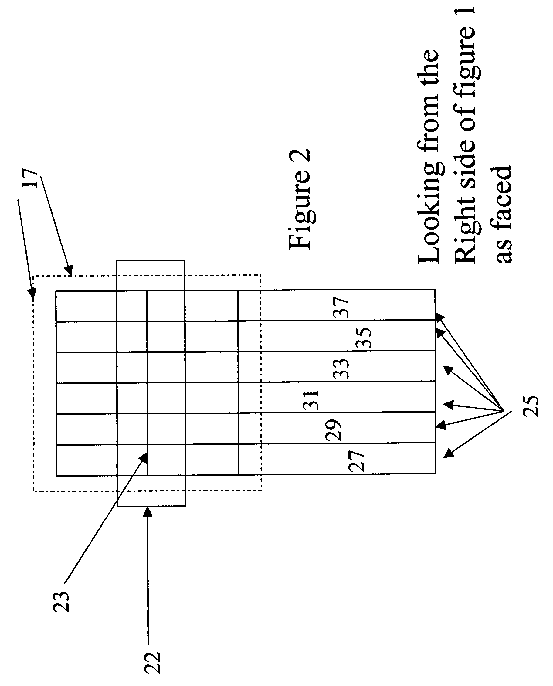
[0028]FIG. 2 shows the ends of a group of six hangers 25 with hook and loop material 17 on the attachment section 13. Located side-by-side, as shown, left to r...

second embodiment

[0029]The alternate embodiment or second embodiment does not use hook and loop material 17 but rather a slotted tube 39 as shown in FIG. 5. The slotted tube 39 is composed of a soft flexible material such as foam rubber, which also provides a soft gripping area.

[0030]As seen in FIG. 4, the slotted tube 39 is placed over the attachment section 13. No cap 22, such as the cap 22, which is used in the first embodiment, is used in the second embodiment. The slotted tube 39 may be closed at the open ends 23 of the attachment section 13. This second embodiment is not secured to the attachment section 13 as firmly as the hook and loop material 17 is secured.

[0031]The slotted tube 39 includes at its lower end 41, adjacent the lower section or the 15 but still within the upper section or the attachment section 13, a pigtail 43 with a snap 45. The pigtail 43 can readily be passed through the clothing section 15 of the group of hangers and then be snapped into the slotted tube 39. This prevents...


PUM


Abstract

This invention includes two embodiments for retaining together a group of several hangers. Each hanger has an attachment section which is shaped like a cane and a clothes section on which clothes are hung. In the first embodiment, hook and loop material is wrapped about the attachment section of several hangers thereby grouping together these hangers. In the alternate embodiment, a slotted tube of soft flexible material is placed over the attachment section of several hangers to hold the hangers together. A pigtail with a snap attached to the slotted tube is passed through the clothing and snapped to itself to prevent the slotted tube from sliding off the clothers hanger.

Description

BACKGROUND OF THE INVENTION[0001]1. Field of the Invention[0002]This invention relates to cloths hangers and, more particularly, to a device for securing a plurality of clothes hangers together while also providing a comfortable grip for holding the plurality of clothes hangers.[0003]2. Description of the Prior Art[0004]The difficulties of carrying several garments on a number of hangers is well known. The pressure of the hanger hooks is uncomfortable and garments slip off the hangers and are hard to control. The difficulties of multiple hangers pertains to hangers both outside of a garment bag and inside a garment bag except that inside a garment bag, the clothes are retained and do not fall on the ground.[0005]The presence of a garment bag is not of significance to this invention as the retention of the hangers into a unitized group whether inside or outside of a garment bag is what is of importance to the current invention.[0006]The prior art teaches the retention of several hang...

Claims


Application Information

Patent Timeline
Patent Type & Authority Applications(United States)
IPC IPC(8): A47H13/00
CPCA47G25/1442A47G25/1457
Inventor NEHER, GEORGE
Owner NEHER GEORGE
Why Eureka
Try Eureka