
Sliding-type portable terminal

a portable terminal and flip-type technology, applied in the field can solve the problems of limited sliding range difficult to secure a distance between the transmitter and the receiver, and the miniaturization of flip-type portable terminals, and achieve the effect of ensuring the sliding rang

Inactive Publication Date: 2008-11-06
SAMSUNG ELECTRONICS CO LTD
View PDF5 Cites 106 Cited by
  • Summary
  • Abstract
  • Description
  • Claims
  • Application Information

AI Technical Summary

Benefits of technology

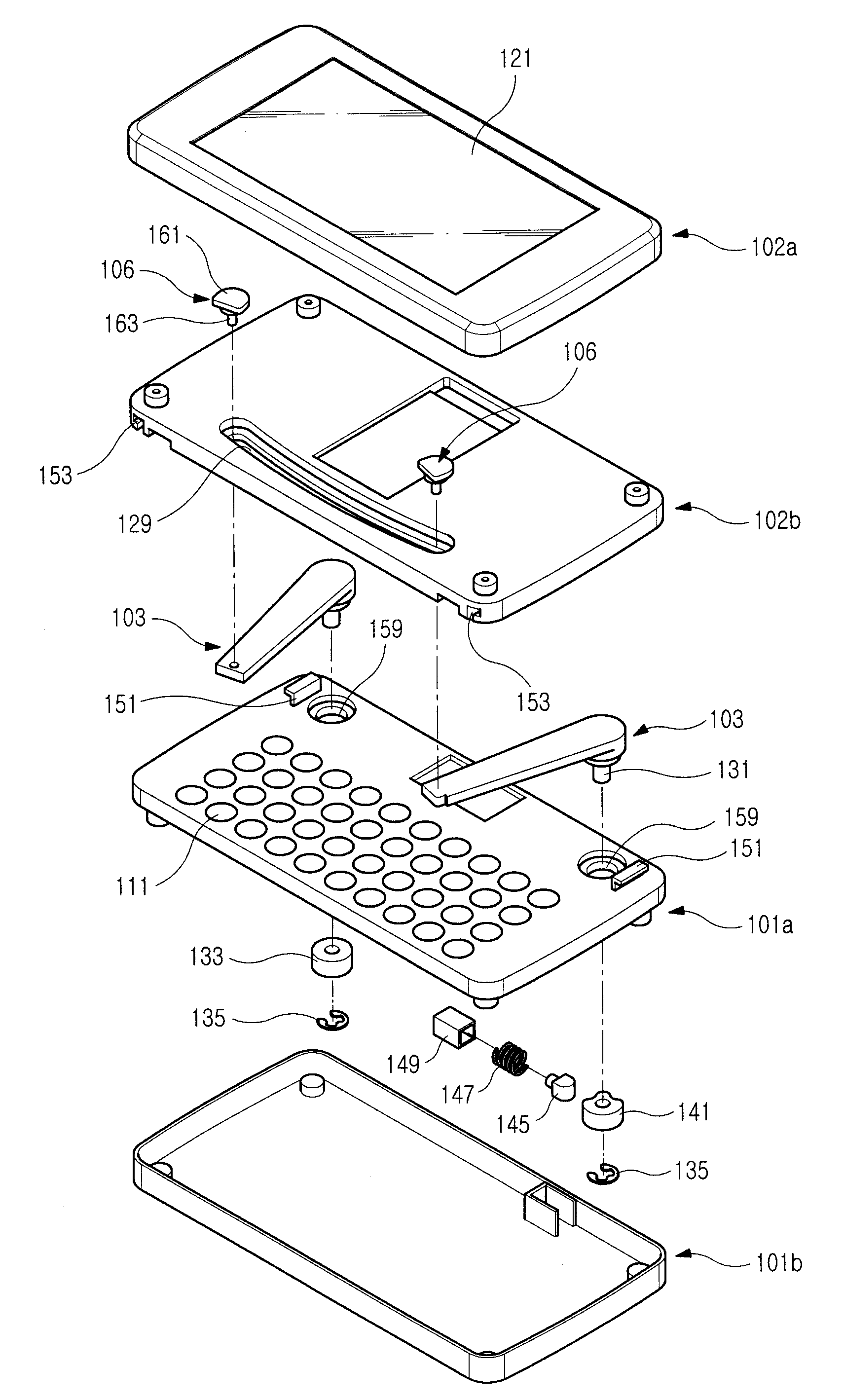
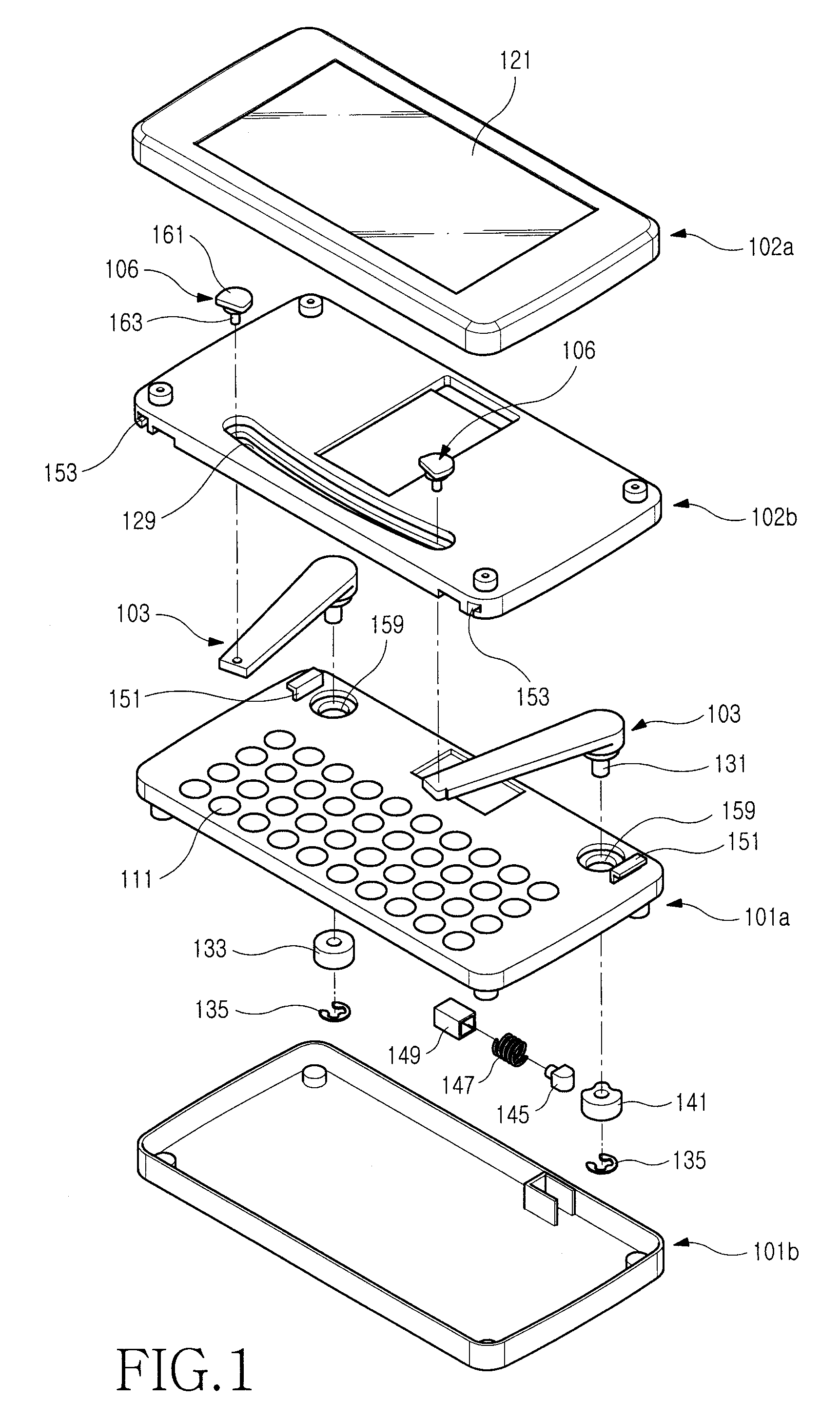
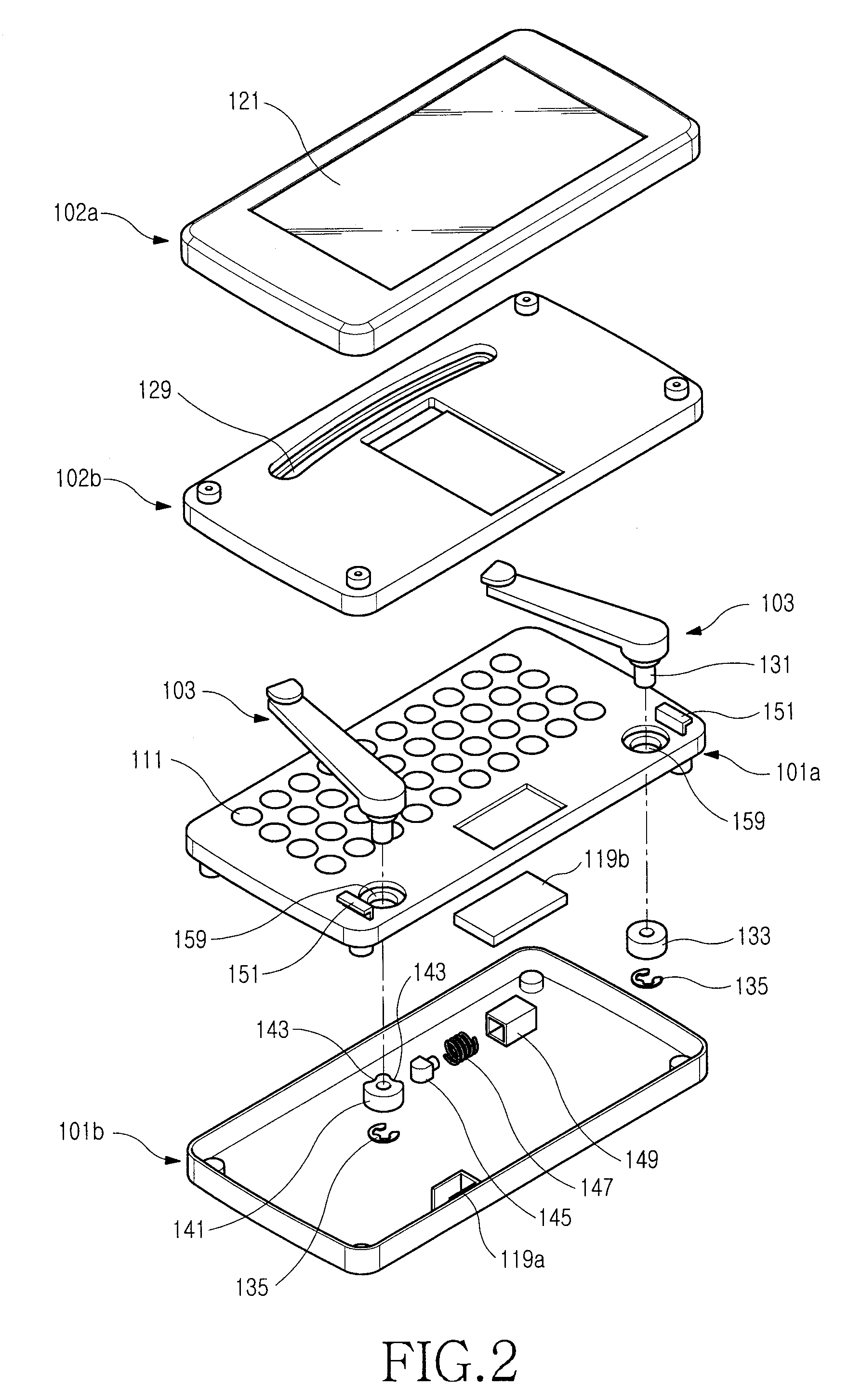
The present invention provides a sliding-type portable terminal that can securely slide and expand the space for mounting an input device or a display device. The terminal includes a first housing, a second housing for sliding while facing the first housing, a pair of link members, and a first guide opening. The link members are engaged with the first guide opening so as to move along the first guide opening as the second housing slides. The technical effects of the invention include stable assembly of the housings, expanded space for mounting an input device or display device, and convenient user experience for multimedia functions such as watching a broadcast.

Problems solved by technology

Although every unit used for the mobile communication function is mounted on the single body housing so that the terminal is simple, there is a limitation in the miniaturization of the portable terminal because it is difficult to secure a distance between the transmitter and receiver.
However, there is also a limitation in the miniaturization of the flip-type portable terminal because it is difficult to secure a distance between the transmitter and the receiver.
However, in the sliding-type portable terminal, the sliding range is limited in order to secure a firm assembling structure.
The above-described sliding-type portable terminal has a problem in that it is difficult to a secure a sufficient space for mounting the input unit, particularly the keypad.
However, that disadvantageously makes the space for mounting the display unit smaller.

Method used


Image

  • Sliding-type portable terminal
  • Sliding-type portable terminal
  • Sliding-type portable terminal

Examples


Embodiment Construction

[0028]The following description with reference to the accompanying drawings is provided to assist in a comprehensive understanding of exemplary embodiments of the invention as defined by the claims and their equivalents. It includes various specific details to assist in that understanding but these are to be regarded as merely exemplary. Accordingly, those of ordinary skill in the art will recognize that various changes and modifications of the embodiments described herein can be made without departing from the scope and spirit of the invention. Also, descriptions of well-known functions and constructions are omitted for clarity and conciseness.

[0029]As illustrated in FIGS. 1 to 4, a sliding-type portable terminal 100 according to an exemplary embodiment of the present invention includes a first housing 101, a second housing 102, and a plurality of link members 103. The plurality of link members 103 enables the first housing 101 and the second housing 102 to be connected. The plural...


PUM


Abstract

A sliding-type portable terminal is provided. The sliding-type portable terminal includes a first housing and a second housing. The second housing faces the first housing and can slide relative to the first housing. The sliding-type portable terminal also includes a pair of link members coupled with the first housing and the second housing. The link members rotate relative to one of the first and second housings. Also provided is a first guide opening formed on the other housing wherein one end of the link members is engaged with the first guide opening so as to move along the first guide opening as the second housing slides. In the sliding-type portable terminal, a pair of housings can be rotatably coupled with each other by means of the link members so as to sufficiently secure a greater range of sliding, and thus a space for mounting an input device, such as a keypad, or the like, is increased.

Description

PRIORITY[0001]This application claims the benefit under 35 U.S.C. §119(a) of a Utility Model Application and a Patent Application which were filed in the Korean Industrial Property Office on May 2, 2007 and assigned Serial No. 10-2007-0042637 and on Jun. 25, 2007 and assigned Serial No. 10-2007-0062358, respectively, the entire disclosures of both of which are hereby incorporated by reference.BACKGROUND OF THE INVENTION[0002]1. Field of the Invention[0003]The present invention relates to a portable terminal. More particularly, the present invention relates to a sliding-type portable terminal, in which a pair of housings is coupled with each other in such a manner that they can linearly move while facing each other.[0004]2. Description of the Related Art[0005]In general, the term “portable terminal” refers to a device that provides a user with a mobile communication function. With the advancement of technology, portable terminals now include complex functions so as to be used as a mu...

Claims


Application Information

Patent Timeline
Patent Type & Authority Applications(United States)
IPC IPC(8): H04M1/00
CPCH04M1/021H04M1/0216H04M1/0237
Inventor CHO, SUNG-CHULJUNG, SOO-IKPARK, MYOUNG-HOON
Owner SAMSUNG ELECTRONICS CO LTD
Learn More