
Remote-Controlled Vehicle Designed to be Mounted on a Support and Capable of Clearing an Obstacle

a remote-controlled vehicle and support technology, applied in the direction of railways, rope railways, trains, etc., can solve the problems of unable to clear certain large obstacles, pass over on its own pylons, vibration dampers or spacers, and the positioning of these sensors in order to access components

Active Publication Date: 2008-11-13
HYDRO QUEBEC CORP
View PDF8 Cites 37 Cited by
  • Summary
  • Abstract
  • Description
  • Claims
  • Application Information

AI Technical Summary

Benefits of technology

The present invention is about a remote-controlled vehicle that can clear obstacles on a support. It consists of a first frame, a second frame, a first motor means, an articulated arm, a wheel, attachment means, a second motor means, a temporary support arm, and a third motor means. The first frame and second frame can move longitudinally and pivot vertically to displace the vehicle. The wheel is a motorized traction wheel that can hold the vehicle on the support. The temporary support arm can hold the vehicle on the support and be raised and lowered vertically. The invention allows for efficient and effective clearing of obstacles on a support.

Problems solved by technology

With regard to the gathering of information, numerous sensors have been developed but the positioning of these sensors, in order to access the components, often remains an important challenge.
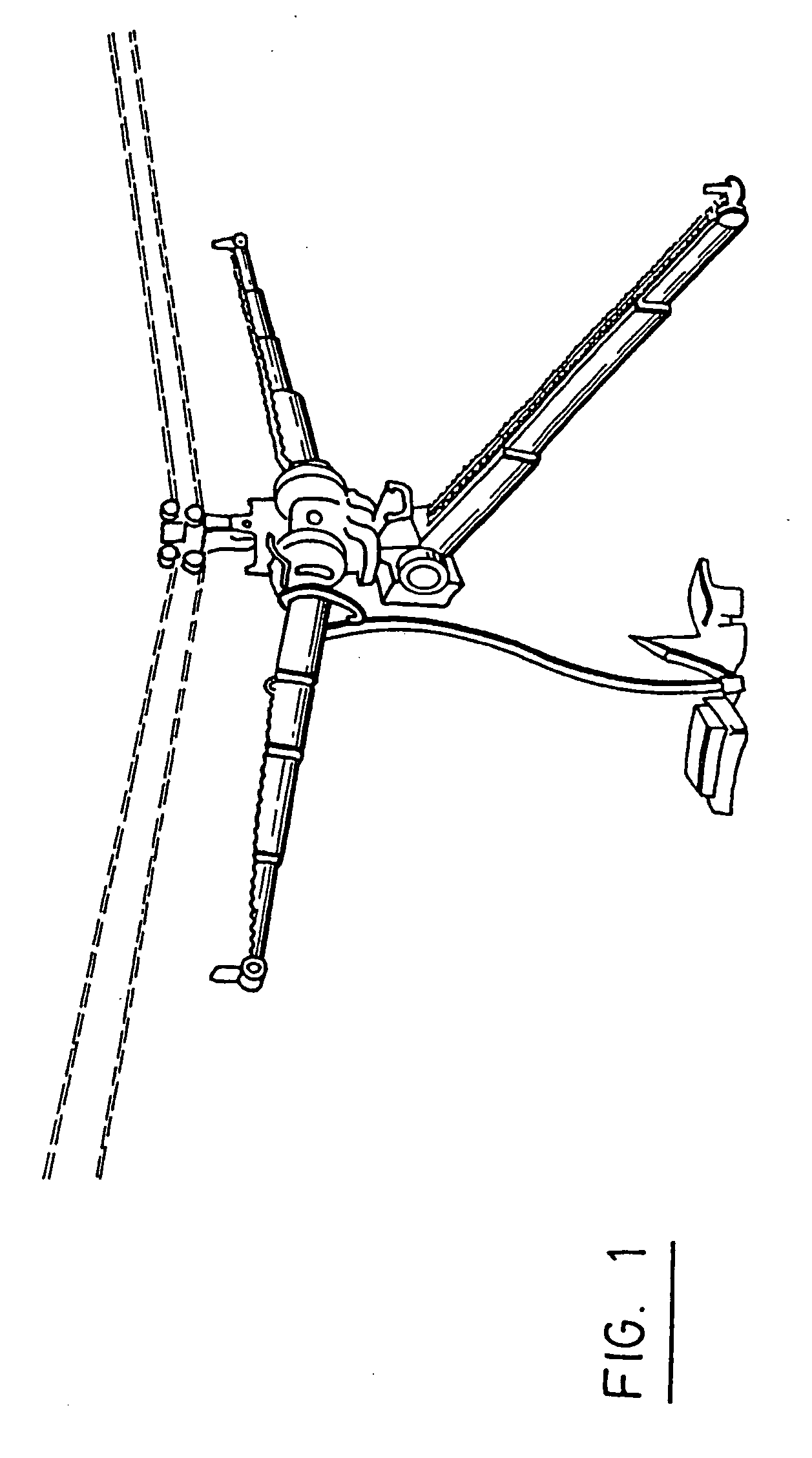
However, even if this type of ROV is capable to pass over mid-span jointing sleeves, it cannot pass over on its own pylons, vibration dampers or spacers.
However, this vehicle cannot clear certain large obstacles such as aerial warning markers that are mounted on certain conductors, on pylons or other diverse objects encountered on the conductive cables.
These last three vehicles are relatively large, heavy, cumbersome, complex and difficult to install.
The configuration of these vehicles tends to make them susceptible to stability and fragility problems.

Method used


Image

  • Remote-Controlled Vehicle Designed to be Mounted on a Support and Capable of Clearing an Obstacle
  • Remote-Controlled Vehicle Designed to be Mounted on a Support and Capable of Clearing an Obstacle
  • Remote-Controlled Vehicle Designed to be Mounted on a Support and Capable of Clearing an Obstacle

Examples


Embodiment Construction

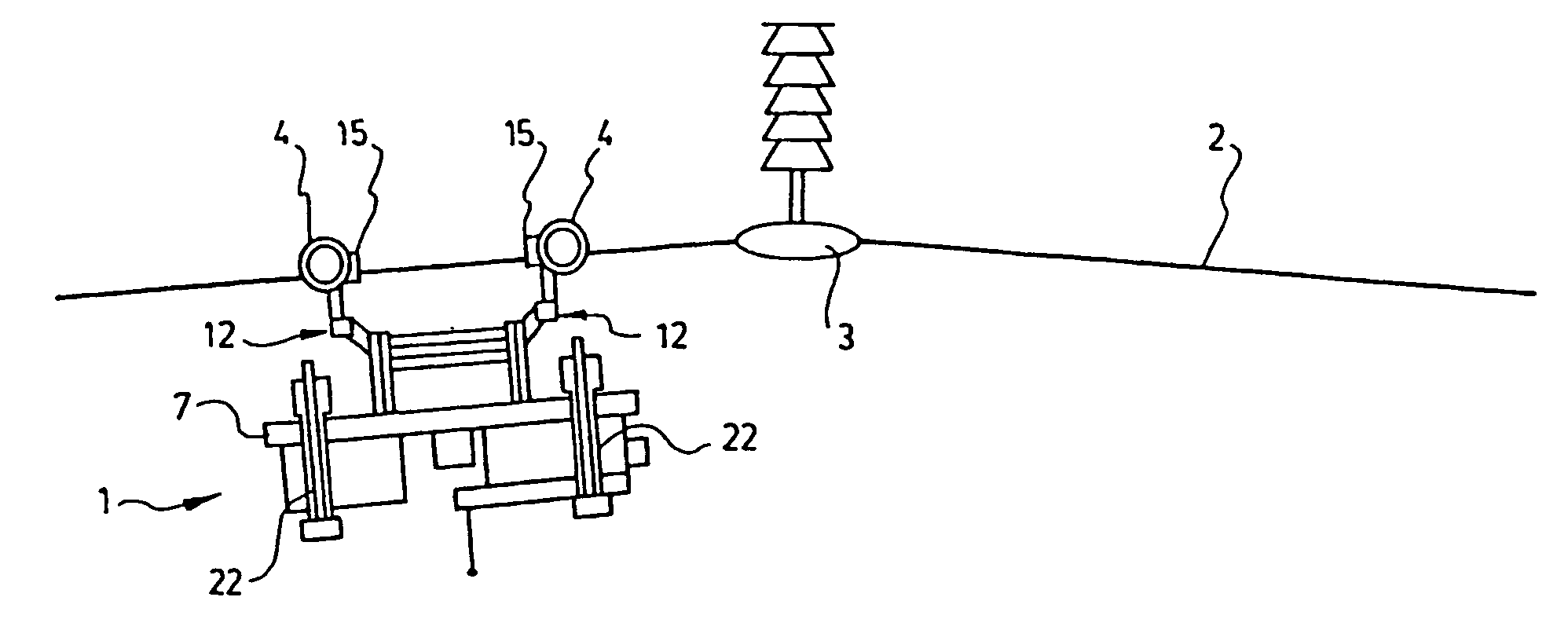
[0047]Referring to FIGS. 3a to 3h, there is shown schematically a remote-controlled vehicle 1, according to a preferred embodiment of the present invention. The vehicle 1 is mounted on a support 2 and proceeds to the clearing of an obstacle 3, according to a preferred method to clear the vehicle 1 with respect to the obstacle 3.

[0048]It is to be noted that the support 2 may be an aerial conductive cable of an electrical distribution network. Of course, people skilled in this field will understand that the support 2 may take many different other forms for other types of applications. For example, the support 2 may be alternatively: a tube containing electrical conductors, a guy wire for supporting a telecommunication tower, a cableway track rope, a tubular structure made of steel (“truss”) being part of the roof of a building, etc. The capacity of the vehicle according to the invention to clear different obstacles in these other contexts may open the door to many other tasks of inspe...


PUM


Abstract

The invention concerns a remote-controlled vehicle designed to be mounted on a support and capable of clearing an obstacle on the support. The vehicle comprises first and second mobile frames. At least one articulated arm is mounted mobile on the first frame and a wheel is mounted on the articulated arm to maintain the vehicle on the support. A fastening means co-operates with the wheel and is adapted to retain the wheel on the support. At least one temporary support arm is mounted mobile on the second frame. The temporary support arm comprises retaining means for maintaining the vehicle on the support. The vehicle comprises motor means connected between the frames and the arms for moving same with respect to one another so as to clear an obstacle encountered on the support.

Description

FIELD OF THE INVENTION[0001]The present invention relates to an improvement to the family of small remote-controlled vehicles designed to travel on aerial conductors, such as those used in the field of transmission of electrical energy, and which may or may not be exposed to live voltages. In English, such vehicles are called: “Remotely Operated Vehicles” or “ROV's”. In particular, the invention relates to mechanical carriers used to transport sensors or existing equipment so as to access the different sections of the conductors.BACKGROUND OF THE INVENTION[0002]The present world context regarding the exploitation of an electrical energy transmission network is the following: ageing components, increasing demand for energy, deregulation and opening of markets, increasing pressure from clients for quality and reliable energy. The electrical utilities are therefore required to know precisely the state of their transmission network in order to apply the principles of preventive maintena...

Claims


Application Information

Patent Timeline
Patent Type & Authority Applications(United States)
IPC IPC(8): B61B7/06H02G1/02
CPCB61B7/06
Inventor MONTAMBAULT, SERGEPOULIOT, NICOLASLEPAGE, MARCOMICHAUD, JACQUESLATULIPPE, PIERRECOMTE, CHRISTOPHE
Owner HYDRO QUEBEC CORP
Learn More