Stationary LED lamp

a technology of led lamps and led lamps, applied in general lighting, mass transit vehicle lighting, lighting support devices, etc., can solve the problems of short life, large load on the engine, and excessive power being used in a wasted way

Inactive Publication Date: 2008-12-11
LIN YU HO
View PDF2 Cites 19 Cited by
  • Summary
  • Abstract
  • Description
  • Claims
  • Application Information

AI Technical Summary

Benefits of technology

[0005]This invention has been devised to offer a stationary LED lamp, which is composed of a heat dissipating strip, a lamp cover base, a LED base, and a support strip. The heat dissipating strip, the lamp cover base and the support strip are all combined tightly together by means of screwing or adhering, The lamp over base is further provided with a reflecting strip on an inner surface and at least more than one LED welded with tin on a PCB (printed circuit board) fixed on the LED base. Then the LED base is adhered with the support strip with heat dissipating cream, with the two ends of the PCB connected with a power line so as to get exterior power.

Problems solved by technology

Recently popular mobile houses are generally provided with conventional lamps such as fluorescent lamps that are stabilized in the base by rotation, More precisely, the two ends of a fluorescent lamp are first inserted in a lamp socket and then rotated to be stabilized therein, However, this kind of stabilizing a lamp is apt to let the lamp loosened, shift or even fall off by vibrations of a sport utility vehicle (SUV) during running on a road, Furthermore, the conventional lamp installed in the SUV is connected to the electricity of the engine, so the conventional lamp cannot have 100% effect in shining, in other words, too excessive power may be used in a wasted way, and it will become a large load for the engine if used for a long term.
Thus the conventional lamp used in a SUV easily wears off, resulting in a short life, needing much expense for its repairing and maintaining for the owner.

Method used


Image

  • Stationary LED lamp
  • Stationary LED lamp
  • Stationary LED lamp

Examples


Embodiment Construction

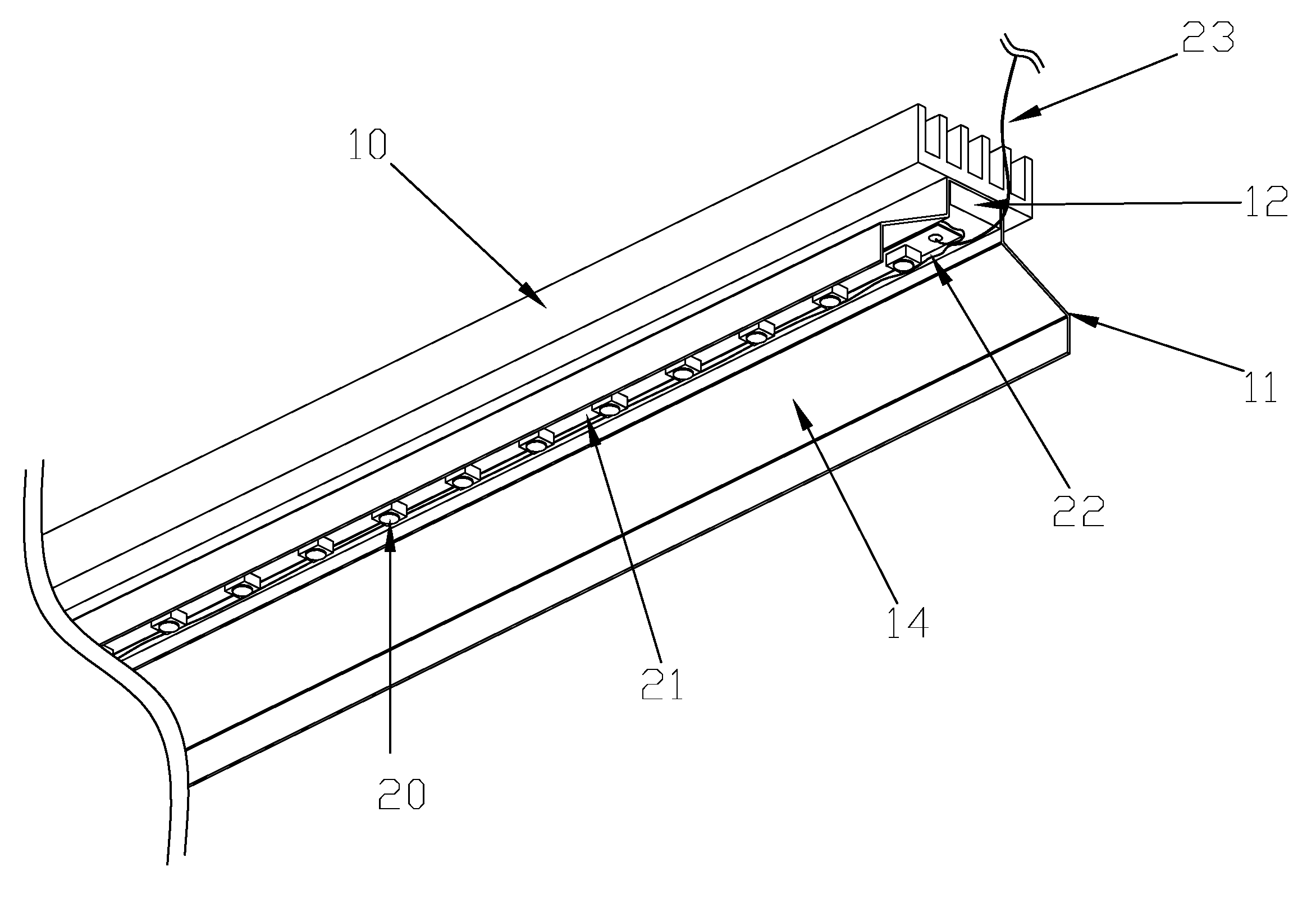
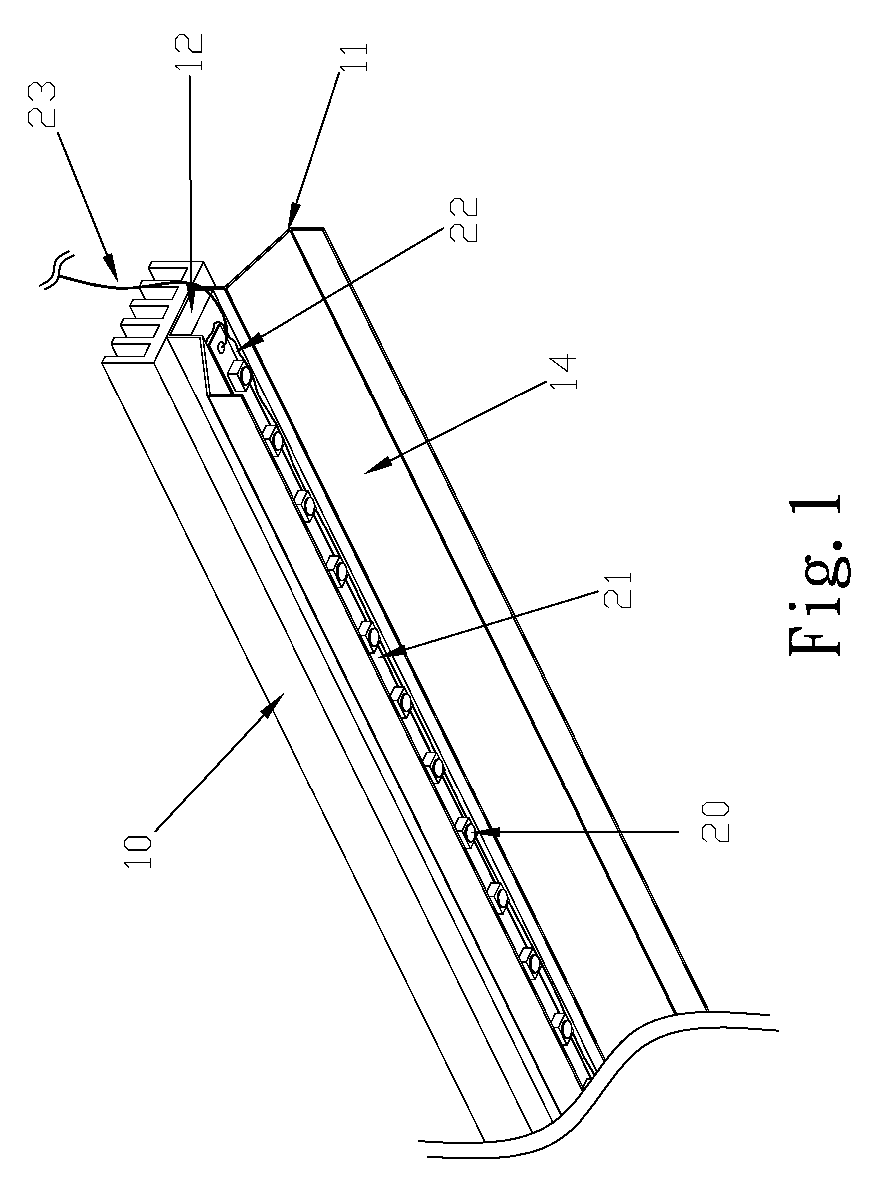
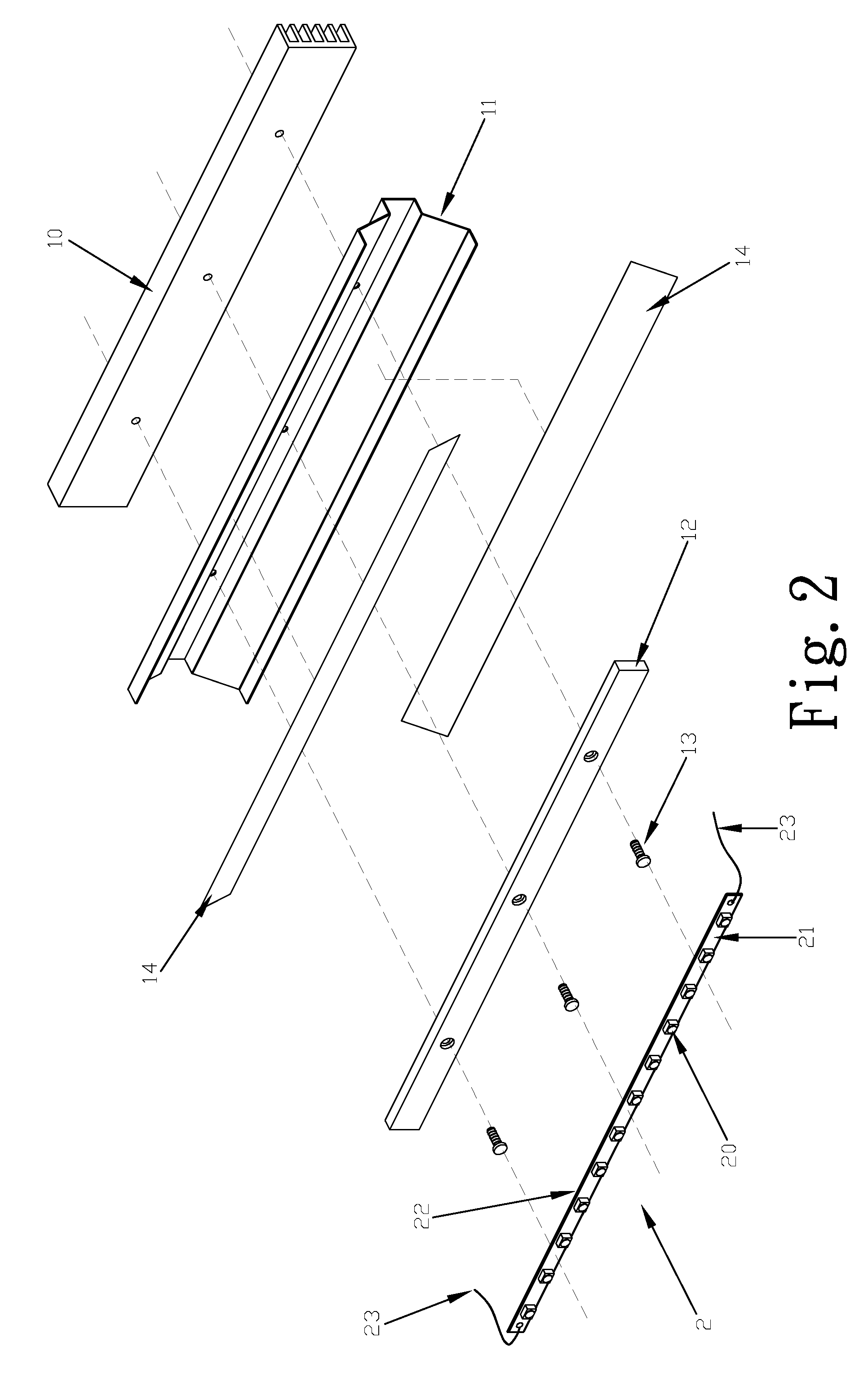
[0009]A preferred embodiment of a stationary LED lamp in the present invention, as shown in FIGS. 1 and 2, includes a heat dissipating strip 10, a lamp cover base 11, a support strip 11, and a lamp base 2 as main components combined together.

[0010]The heat dissipating strip 10, the lamp cover base 11 and the support strip are all provided with a plural screw holes properly spaced apart to correspond with each other, so screws 13 may screw up from below first through the screw holes of the support strip 12, then through the screw holes of the lamp cover base 11 and then with the screw holes of the heat dissipating strip 10. Thus the support strip 12, the lamp cover base 11 and the heat-dissipating strip 10 are combined together.

[0011]Next, the lamp cover base 11 has its inner surface adhered with a reflecting strip 14.

[0012]The LED base 2 has a thin PCB 21 strip made of metal, at least more than one LED 20 of high power welded on the PCB strip 21, which is then connected to the suppo...


PUM


Abstract

A stationary LED lamp includes a heat dissipating strip, a lamp cover base, a support strip, and an LED base. The heat-dissipating strip is adhered at an outer side of the lamp cover base, and the support strip is installed at an inner surface of the lamp cover base, which is provided with a reflecting strip on the inner surface. The LED base is provided with more than one LED welded on a PCB, and then adhered at an inner side of the support strip. Then the LED lamp is positioned by means of screwing or adhering, without easily loosening off as a conventional lamp does. The stationary LED lamp has a high luminance and swift heat dissipation to comply with the environment protection more effectively than the conventional one does.

Description

BACKGROUND OF THE INVENTION[0001]1. Field of Invention[0002]This invention relates to a stationary LED lamp, particularly to one making use of LED as a light source matched with a heat dissipating strip combined with a light cover base by adhering or screwing, not easily loosening off, saving electricity, having high efficacy so as to take place of conventional lights using rotation for stabilizing.[0003]2. Description of the Related Art[0004]Recently popular mobile houses are generally provided with conventional lamps such as fluorescent lamps that are stabilized in the base by rotation, More precisely, the two ends of a fluorescent lamp are first inserted in a lamp socket and then rotated to be stabilized therein, However, this kind of stabilizing a lamp is apt to let the lamp loosened, shift or even fall off by vibrations of a sport utility vehicle (SUV) during running on a road, Furthermore, the conventional lamp installed in the SUV is connected to the electricity of the engine...

Claims


Application Information

Patent Timeline
Patent Type & Authority Applications(United States)
IPC IPC(8): F21V29/00
CPCB60Q3/025F21S4/008F21S48/328F21V7/005F21V29/763F21V21/0808F21V29/004F21Y2101/02F21Y2103/003F21V19/005F21S4/28F21Y2103/10F21Y2115/10B60Q3/43F21S45/47
Inventor LIN, YU-HO
Owner LIN YU HO
Why Eureka
Try Eureka