Sign support structures

a technology of support structure and sign, applied in the direction of signs, instruments, machine supports, etc., can solve the problem of not being able to insert real estate signs into the ground

Inactive Publication Date: 2008-12-18
ULLOA JOSE J +1
View PDF24 Cites 43 Cited by
  • Summary
  • Abstract
  • Description
  • Claims
  • Application Information

AI Technical Summary

Benefits of technology

[0005]According to the principle of the invention, a sign support structure consists of an upstanding wall including an upper end and opposed substantially parallel first and second faces extending downwardly from either side of the upper end. Further to the present embodiment are a fixture, a first elongate support, and a second elongate support. The fixture includes a base having opposed first and second ends, opposed first and second sides extending between the opposed first and second ends, and opposed upper and lower faces, the first and second ends and the first and second sides cooperating to form a perimeter of the base. Opposed, substantially parallel first and second endwalls are affixed to the first and second ends, respectively, of the base. The first and second endwalls extend downwardly relative to the lower face of the base and each have an outer face and an opposed inner face. The inner faces of the first and second endwalls and the lower face of the base cooperate to form a receiving area of the fixture. A setting element is held by the first endwall. The wall is received in the receiving area, in which the upper end of the wall is received against the lower face of the base, the inner face of the first endwall confronts the first face of the wall, and the inner face of the second endwall confronts the second face of the wall. The setting element held by the first endwall is applied against the first face of the wall to urge the inner face of the second endwall against the second face of the wall to secure the fixture to the wall. The first elongate support has a lower end affixed to the fixture and extends upwardly relative to the upper face of the base of the fixture to an upper end. The second elongate support has an inner end mounted to the first elongate support adjacent to the upper end of the first elongate support and extends laterally outward from the first elongate support to an outer end. The second elongate support is adapted to hold a real estate sign. The lower end of the first elongate support is, in accordance with a preferred embodiment, affixed to the base of the fixture. The setting element has an abutment end located in the receiving area and is mounted to the first endwall for movement between a first position of the abutment toward the first endwall away from the second endwall and a second position away from the first endwall toward the second endwall. In accordance with the present embodiment, the setting element is disposed substantially in the second position of the abutment to apply the abutment against the first face of the wall to urge the inner face of the second endwall against the second face of the wall to secure the fixture to the wall. In a particular embodiment, the abutment of the setting element is adjustable between the first and second positions thereof in response to rotation of the setting element.

Problems solved by technology

Typical real estate sign posts are simply driven into the ground, which is often quite difficult.
Moreover, in many instances planting a real estate sign into the ground is simply not possible, or results in the real estate sign positioned at a location that is not optimized to effectively communicate the real estate sign to potential customers.

Method used


Image

  • Sign support structures
  • Sign support structures
  • Sign support structures

Examples


Embodiment Construction

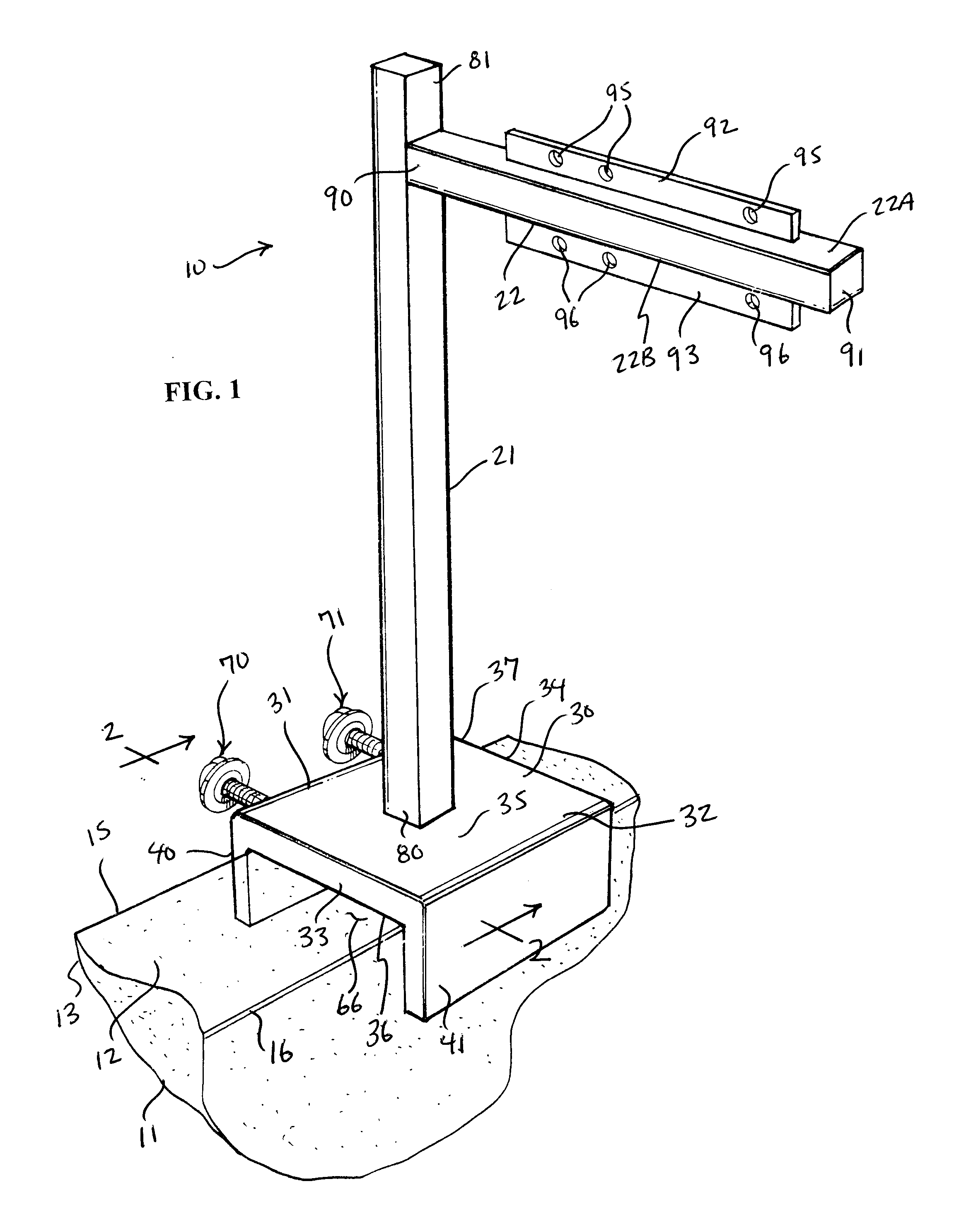
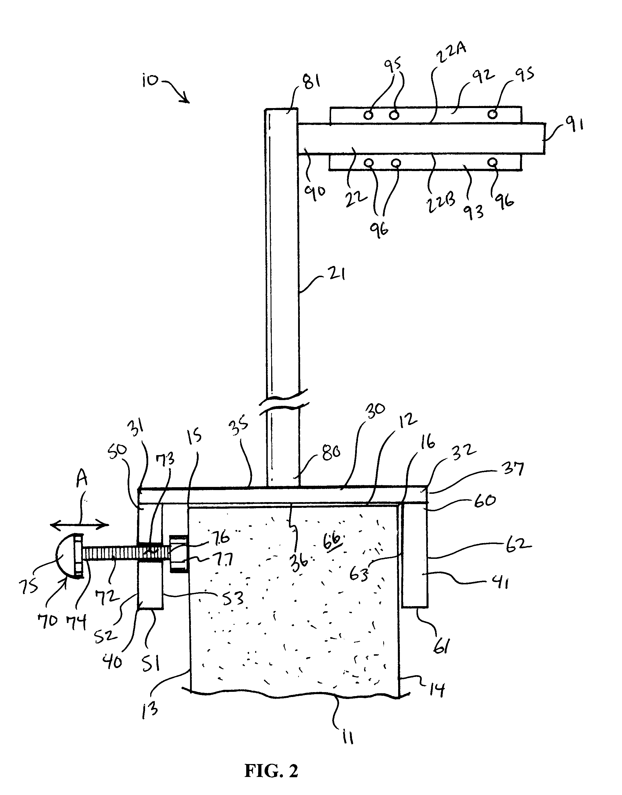
[0018]Turning now to the drawings, in which like reference characters indicate corresponding elements throughout the several views, attention is first directed to FIGS. 1 and 2 in which there is seen a sign support structure 10 in combination with an upstanding wall 11 including an upper end 12 and opposed substantially parallel first and second faces 13 and 14 extending downwardly from sides 15 and 16, respectively, of upper end 12. Sign support structure 10 consists of a fixture 20, a first elongate support 21, and a second elongate support 22. Sign support structure 10 is used to support a real estate sign, and is fashioned of steel, aluminum, plastic, or other substantially rigid material or combination of materials.

[0019]Fixture 20 includes a base 30, which is broad and flat and generally square in shape, has opposed first and second ends 31 and 32, opposed first and second sides 33 and 34, illustrated in FIG. 1, extending between the opposed first and second ends 31 and 32, an...


PUM


Abstract

A sign support structure includes a broad base plate having opposed upper and lower faces, and a perimeter edge. Substantially equally spaced-apart openings are formed through the base plate along the perimeter from the upper face to the lower face to receive stakes, respectively, to secure the base plate to the ground. A first elongate support has an upper end and an opposed lower end mounted to the base. The first elongate support extends upwardly from the upper face of the base to the upper end. A second elongate support has an inner end mounted to the first elongate support adjacent to the upper end of the first elongate support and extends laterally outward relative to the first elongate support to an outer end. The second elongate support is adapted to hold a real estate sign.

Description

CROSS-REFERENCE TO RELATED APPLICATION[0001]This application claims the benefit of U.S. Provisional Patent Application Ser. No. 60 / 934,547, filed Jun. 14, 2007.FIELD OF THE INVENTION[0002]The present invention relates to real estate sign support structures.BACKGROUND OF THE INVENTION[0003]Real estate signs are often used to advertise the sale or lease of a particular piece of property. Typical real estate signs include a vertical post with a horizontal cross-arm which holds an advertising panel displaying information about the sale or lease. This information can include contact information such as the name of the person handling the lease or sale of the property. For effective advertising, the sign should be prominently displayed, readable from a distance, and should catch the prospective buyer or leaser's attention.[0004]Typical real estate sign posts are simply driven into the ground, which is often quite difficult. Moreover, in many instances planting a real estate sign into the ...

Claims


Application Information

Patent Timeline
Patent Type & Authority Applications(United States)
IPC IPC(8): G09F15/00
CPCG09F7/18G09F15/0018G09F17/00
Inventor ULLOA, JOSE J.ULLOA, PAULINE R.
Owner ULLOA JOSE J
Why Eureka
Try Eureka