

Adjustable grinder
a grinder and adjustment technology, applied in the field of adjustmentable grinders, can solve the problems of not being able to identify the grinding fineness, not being able to provide marks, and the device typically does not permit continuous adjustment of the ground produ
- Summary
- Abstract
- Description
- Claims
- Application Information
AI Technical Summary
Problems solved by technology
Method used
Image

Examples
Embodiment Construction
[0031]Certain terminology is used in the following description for convenience only and is not limiting. The words “above,”“below,”“lower,” and “upper” designate directions in the drawings to which reference is made. The terminology includes the words noted above as well as derivatives thereof and words of similar import.
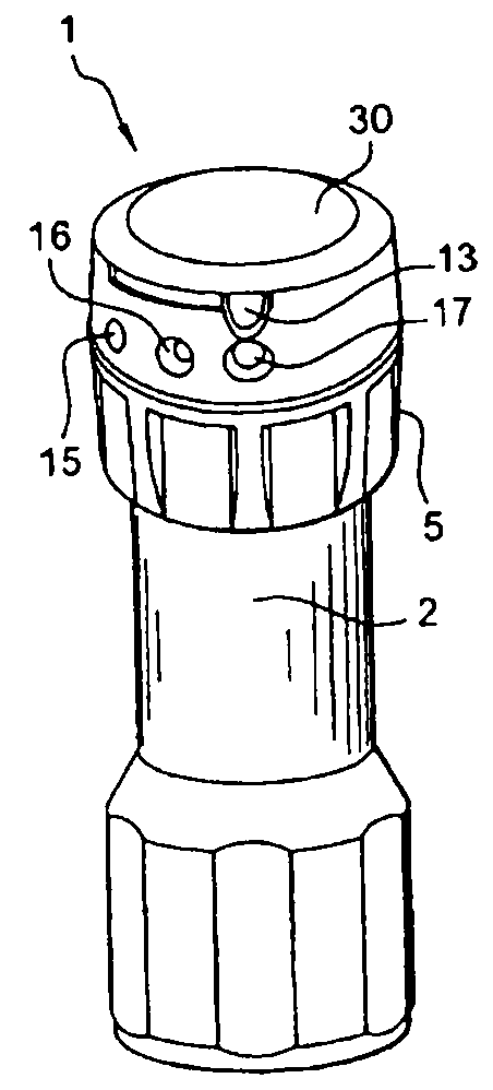
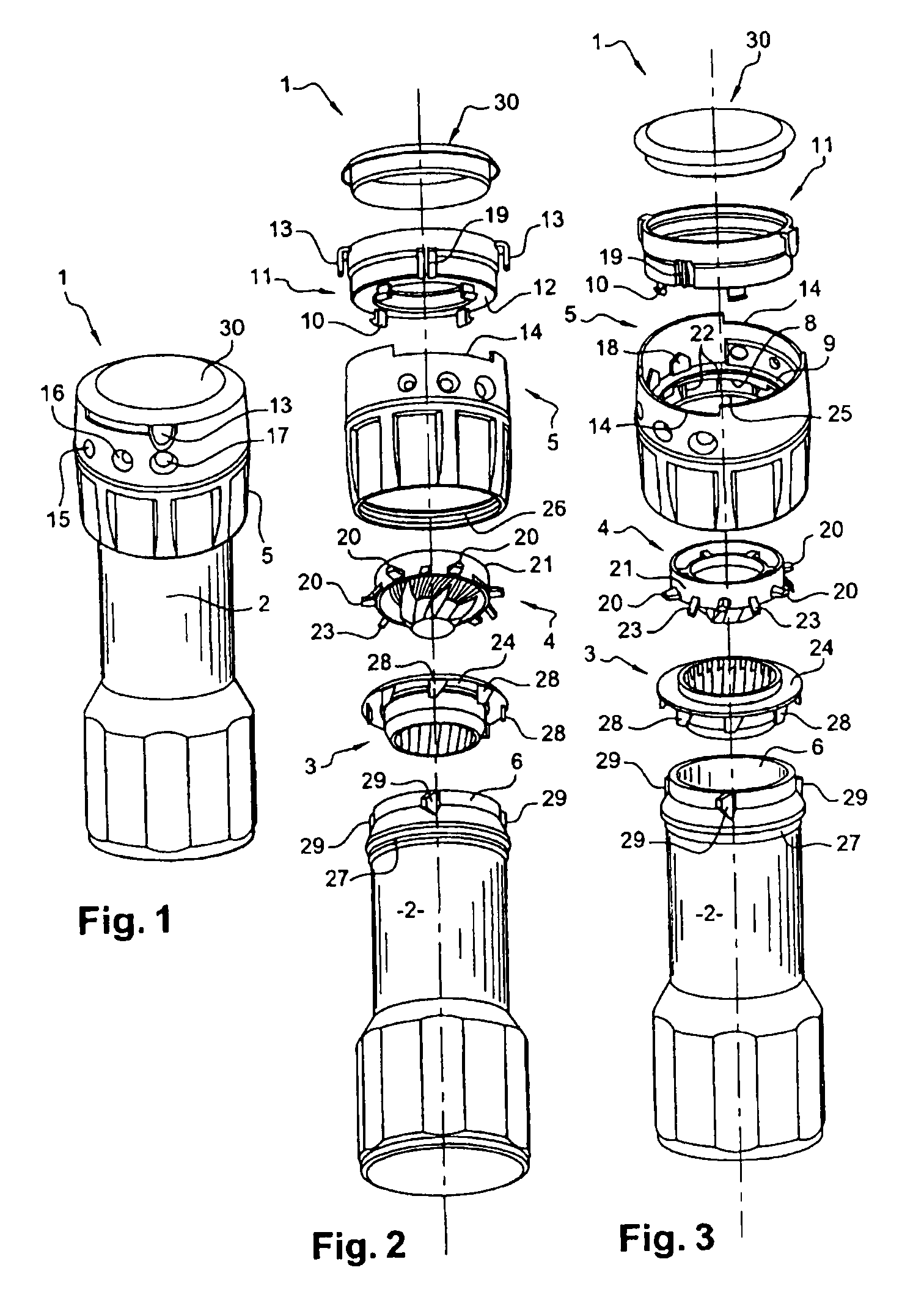
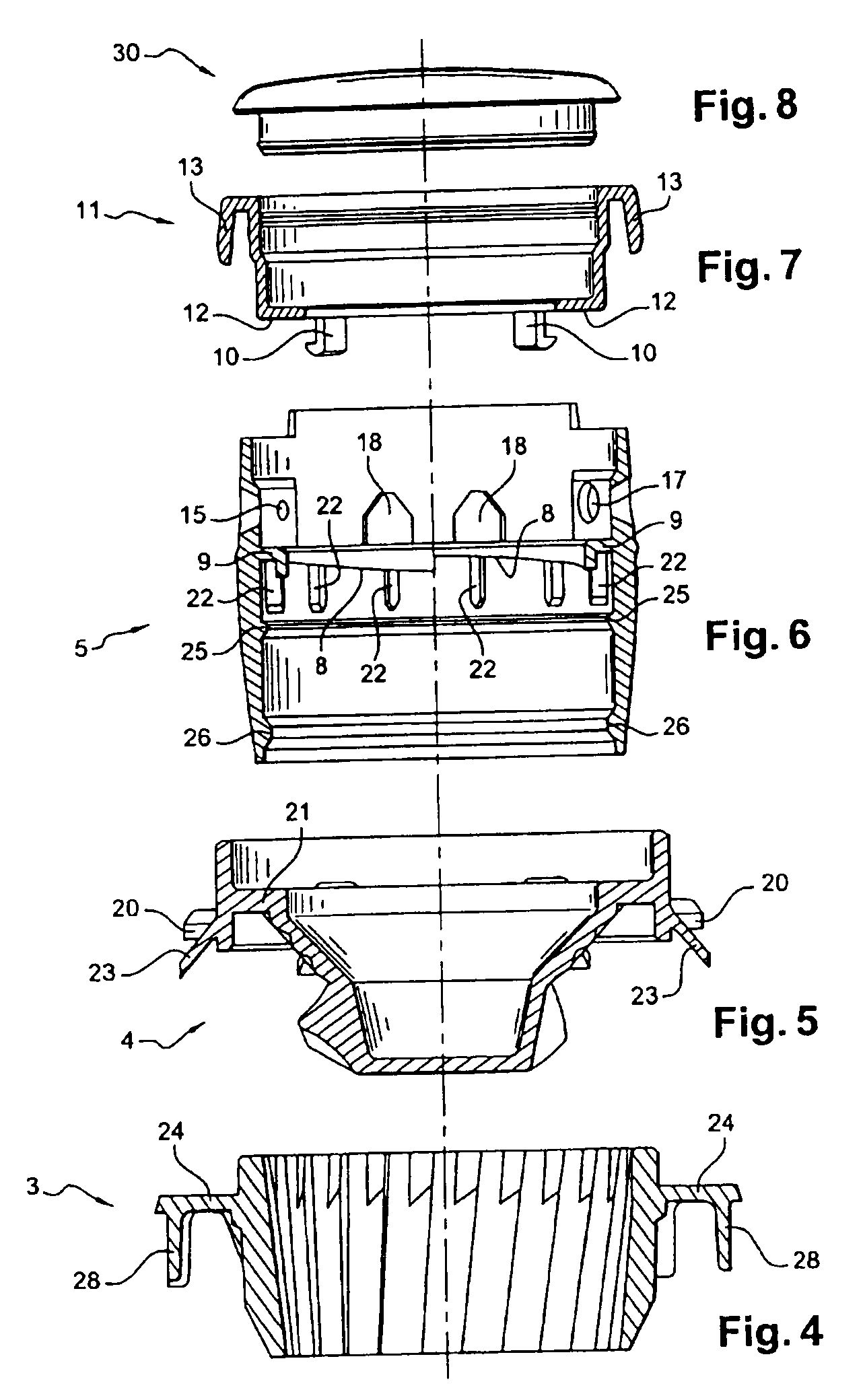
[0032]An adjustable grinder can contain grain-like condiments, such as pepper, salt, and berries, in a container. As shown in FIGS. 1-9, an adjustable grinder can include a grinding device, such as a stator 3, which can be fitted on a container, such as a reservoir 2. A rotor 4 can be provided opposite to the stator 3. The rotor 4 has at least one row of teeth 31 (see FIG. 14) on the surface facing the stator 3 that can grind the product contained in the adjustable grinder 1. Additionally, the rotor 4 has a plurality of fingers 33 (see FIG. 14) that can distribute a product to the teeth 31. As shown in FIG. 14, the fingers 33 may be helicoidal to help direct the pro...
PUM
 Abstract
Description
Claims
Application Information