System and method for reducing visible speckle in a projection visual display system

a visual display and projection system technology, applied in the field of projection visual display systems, can solve the problems of face constraints associated with providing such increased resolution and brightness, and light sources often produce images with noticeable granularity, so as to reduce visible speckle reduce visible speckle

Active Publication Date: 2009-01-08
TEXAS INSTR INC
View PDF8 Cites 5 Cited by
  • Summary
  • Abstract
  • Description
  • Claims
  • Application Information

AI Technical Summary

Benefits of technology

[0007]In another aspect, the invention provides a method of reducing visible speckle in a PVD system. In one embodiment, the method includes interposing a diffuser in an optical path of the PVD system and applying a force along a single drive axis to cause the diffuser to travel in a lissajous curve at least partially transverse to the optical path.
[0008]In yet another aspect, the invention provides a PVD system. In one embodiment, the system includes: a light modulator configured to generate real-time images from an input image signal, a screen configured to display the images and a projection lens configured to project the images from the light modulator onto the screen. The screen has an apparatus for reducing visible speckle in the PVD system, including: a diffuser interposed in an optical path of the projection visual display system, a spring system coupled to the diffuser and a fixed member of the PVD system, and a diffuser actuator having a single drive axis and configured to cause the diffuser to travel in a lissajous curve at least partially transverse to the optical path.
[0009]In still yet another aspect, the disclosure provides another embodiment of an apparatus for reducing visible speckle in a PVD system. In this embodiment, the apparatus includes a diffuser interposable in an intermediate image plane of an optical path of the PVD system, a spring coupled to the diffuser and a diffuser actuator coupled to the spring and configured to apply a force to the spring along a single drive axis that is offset from a center of mass of the diffuser and cause the diffuser to travel in a lissajous curve at least partially transverse to the optical path.

Problems solved by technology

Engineers continue to try to increase the resolution and brightness of imaging systems to provide better picture quality, but also face constraints associated with providing such increased resolution and brightness.
However, while coherent light sources may increase the brightness of the PVD system, such light sources often produce images having a noticeable granularity.

Method used


Image

  • System and method for reducing visible speckle in a projection visual display system
  • System and method for reducing visible speckle in a projection visual display system
  • System and method for reducing visible speckle in a projection visual display system

Examples


Embodiment Construction

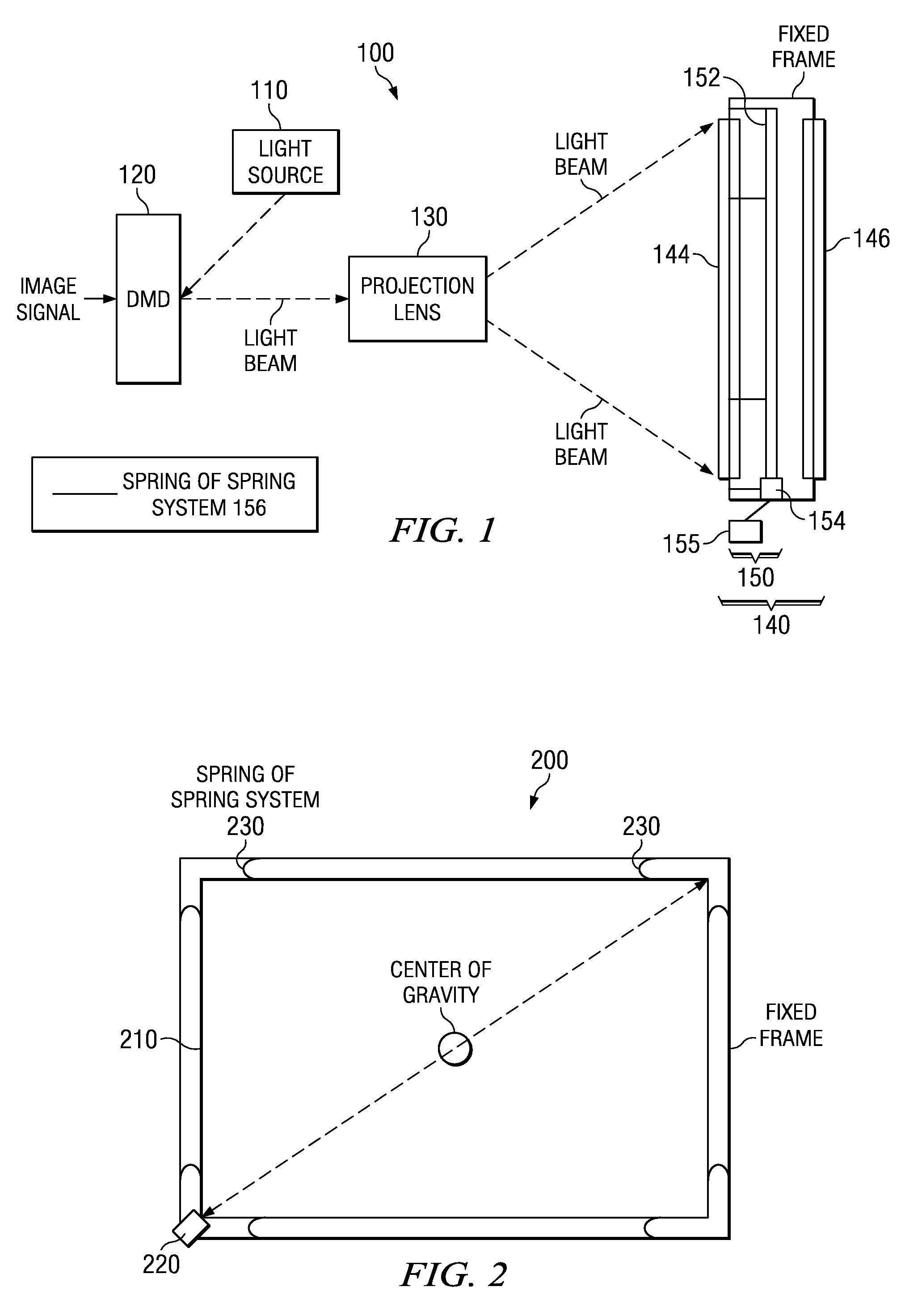
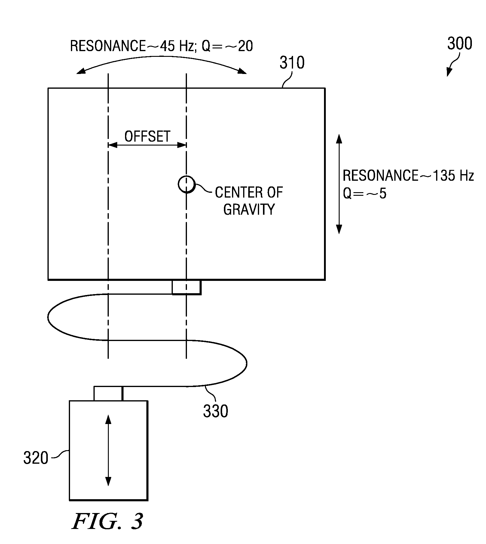
[0016]In general, a diffuser traveling in a lissajous curve in response to a force exerted thereon along a single axis (single drive axis) is provided to reduce visible speckle. The diffuser will not stop, even instantaneously, as long as the diffuser actuator is being driven since the resonant frequencies of the two axes of motion of the lissajous curve are at an integer ratio and remain commensurate over time. The phases of the two axes are independently controlled since they are at different frequencies.

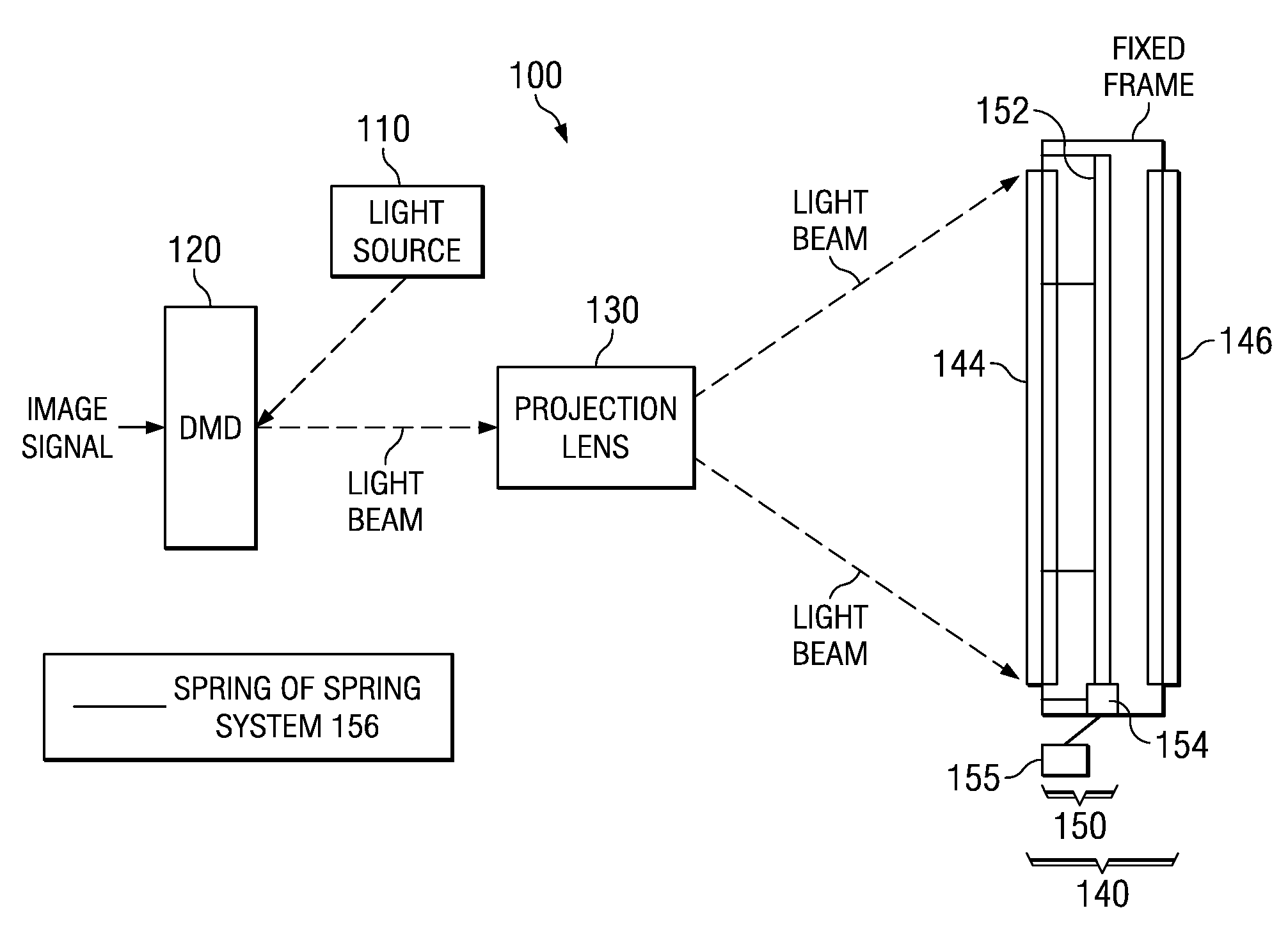
[0017]To reduce visible speckle, one embodiment of the invention calls for a moving low-angle diffuser to be placed in the optical path (i.e., at the display screen) or at an image plane in the optical path of a PVD system, such as a television or cell phone. The optical path is the path of a light beam, used for generating an image in a PVD system, as the light beam travels through the PVD. The diffuser may be coupled with a single-axis drive mechanism (a diffuser actuator) throu...


PUM


Abstract

The invention provides an apparatus for reducing speckle in a projection visual display (PVD) system, a method of reducing visible speckle in a PVD system and a PVD system incorporating the method or apparatus. In one embodiment, the apparatus includes a diffuser interposable in an optical path of a PVD system and a diffuser actuator having a single drive axis configured to cause the diffuser to travel in a lissajous curve at least partially transverse to the optical path.

Description

CROSS-REFERENCE TO PROVISIONAL APPLICATION[0001]This application claims the benefit of U.S. Provisional Application Ser. No. 60 / 947,640, filed on Jul. 2, 2007, and incorporated herein by reference in its entirety.TECHNICAL FIELD OF THE INVENTION[0002]The invention is directed, in general, to projection visual display (PVD) systems and, more specifically, to a system and method employing a diffuser that moves the diffuser in a particular manner to reduce visible speckle that may be evident in such systems.BACKGROUND OF THE INVENTION[0003]Televisions and other types of imaging systems are pervasive in today's society. Recent years have seen the introduction of higher definition imaging systems. Engineers continue to try to increase the resolution and brightness of imaging systems to provide better picture quality, but also face constraints associated with providing such increased resolution and brightness.[0004]For example, to increase brightness in PVD systems, coherent light sources...

Claims


Application Information

Patent Timeline
Patent Type & Authority Applications(United States)
IPC IPC(8): G02B5/02
CPCG03B21/56
Inventor DUNPHY, JAMES C.MARSHALL, STEPHEN W.
Owner TEXAS INSTR INC
Why Eureka
Try Eureka