
System and method for displaying images

a technology of system and method, applied in the field of system and method for displaying images, can solve the problems of reducing affecting the effect of image quality, and affecting the quality of images, so as to reduce the visible speckle in images

Active Publication Date: 2010-08-24
TEXAS INSTR INC
View PDF17 Cites 7 Cited by
  • Summary
  • Abstract
  • Description
  • Claims
  • Application Information

AI Technical Summary

Benefits of technology

[0009]These and other problems are generally solved or circumvented, and technical advantages are generally achieved, by embodiments of a system and a method for reducing visible speckle in images displayed using coherent light.
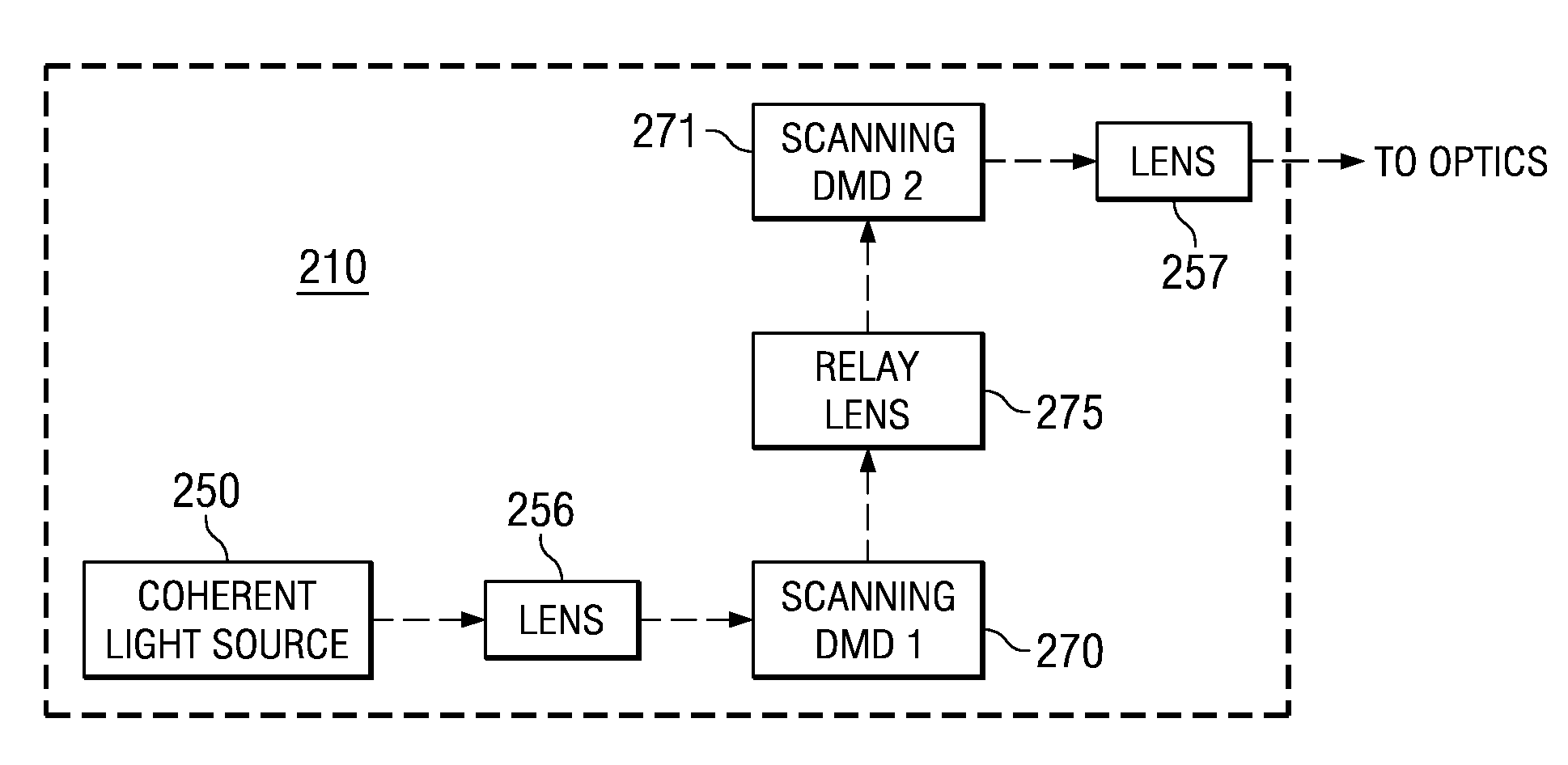
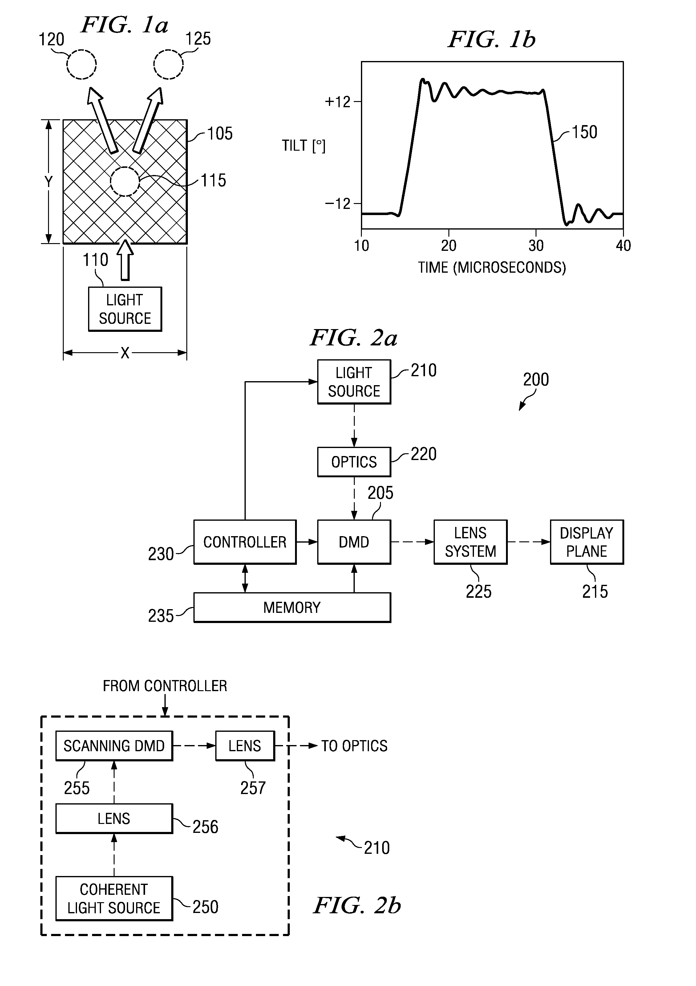
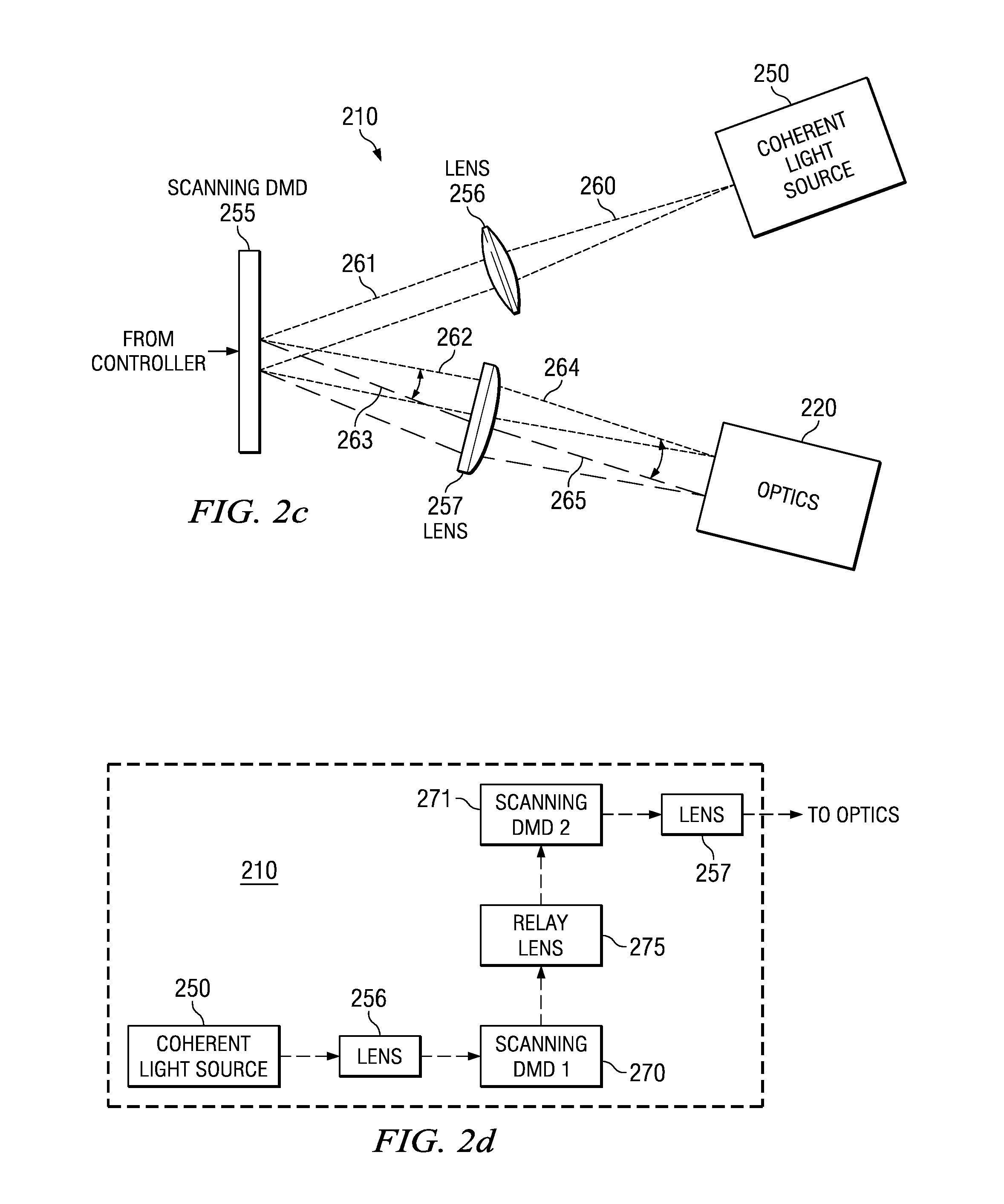
[0013]An advantage of an embodiment is that the use of a digital micromirror device (DMD) to steer the coherent light beams enables the rapid movement of the coherent light beams with large optical aperture and wide steering angle, all of which may help significantly reduce speckle.
[0014]A further advantage of an embodiment is that DMDs enable mass fabrication. This may significantly reduce the cost of the speckle reduction hardware, thereby minimizing impact on the overall cost of an imaging system containing the speckle reduction hardware. Additionally, DMDs are integrated circuits and typically offer greater reliability than discrete components.
[0015]Yet another advantage of an embodiment is that DMDs utilize low drive power, and there exists a mature set of support electronics. Therefore, implementing a DMD-based speckle reducing technique may be simpler and may be developed with a smaller time investment and with a lower monetary investment than other alternatives.
[0016]Yet another advantage of an embodiment is that the DMDs may be partitioned into groups of micromirrors that may be operated independently and asynchronously to create multiple independent beams of coherent light that may continuously scan the entirety of the angular scan zone in a random fashion, further reducing the appearance of speckles.
[0017]Yet another advantage of using DMDs is the fact that even if some micromirrors may not be operating as desired, they may not contribute to lost light, since light from the DMD may be captured in all tilt angle orientations of the micromirrors resulting in a system with a high degree of fault tolerance.

Problems solved by technology

When coherent light is scattered by a rough surface, such as a display plane, a modulating spatial noise with high contrast may be produced.
The modulating spatial noise, commonly referred to as speckle, may be highly objectionable to viewers.
Galvanometric mirrors offer a variety of optical aperture sizes and wide steering angles, but are slower in speed as compared to acousto-optic deflectors and have a non-linear scan response time.

Method used


Image

  • System and method for displaying images
  • System and method for displaying images
  • System and method for displaying images

Examples


Embodiment Construction

[0031]The making and using of the embodiments are discussed in detail below. It should be appreciated, however, that the present invention provides many applicable inventive concepts that can be embodied in a wide variety of specific contexts. The specific embodiments discussed are merely illustrative of specific ways to make and use the invention, and do not limit the scope of the invention.

[0032]The embodiments will be described in a specific context, namely a DMD-based image display system illuminated by coherent light, such as from a laser light source. The embodiments may also be applied, however, to other image display systems illuminated by coherent light, such as those utilizing transmissive or reflective liquid crystal displays, liquid crystal on silicon, ferroelectric liquid-crystal-on-silicon, deformable micromirrors, and other forms of microdisplays and spatial light modulators. Additionally, the embodiments may be applied to other applications where the ability to steer...


PUM


Abstract

A system and method for reducing visible speckle in images displayed using coherent light. In an embodiment, a system for displaying images includes a light source to produce coherent light, an array of light modulators optically coupled to the light source and positioned in a light path of the light source after the light source, and a controller electronically coupled to the array of light modulators and to the light source. The light source includes a coherent light source, and a first digital micromirror device (DMD) having a first plurality of micromirrors. The first DMD is optically coupled to the coherent light source and positioned in a light path of the coherent light source after the coherent light source. The first DMD directs coherent light by moving the micromirrors of the first plurality of micromirrors through a first range of tilt angles substantially continuously.

Description

TECHNICAL FIELD[0001]The present invention relates generally to a system and method for displaying images, and more particularly to a system and method for reducing visible speckle in images displayed using coherent light.BACKGROUND[0002]A coherent light source, such as a laser, may be used to replace a wideband light (light that encompasses a wide range of wavelengths) source, such as a lamp, and / or a narrowband light (light that encompasses a small range of wavelengths) source, such as a light emitting diode (LED), in projection display systems. When a wideband light source is used in a projection display system, color filters may generally be used to create light with desired colors (wavelengths). The use of a narrowband light source may eliminate the color filter. For example, in a projection display system, such as a microdisplay-based projection display system, narrowband coherent light at desired wavelengths produced by multiple lasers may replace a wideband light produced by...

Claims


Application Information

Patent Timeline
Patent Type & Authority Patents(United States)
IPC IPC(8): G02B26/00
CPCH04N9/3161H04N9/3197
Inventor KHAN, SAJJAD ALIBARTLETT, TERRY ALAN
Owner TEXAS INSTR INC
Learn More