Laser mask for creating a corneal pocket

Inactive Publication Date: 2009-01-08
PRESBIBIO +1
16 Cites 7 Cited by

AI-Extracted Technical Summary

Problems solved by technology

However, such surgical reshaping is not reversible, resulting in some risk of creating permanent visual aberrations for the patient.
Nevertheless, the surgical preparation of such a pocket for an intracorneal lens is difficult to perform accurately.
A number of challenges are presented by the surgical procedures used to create corneal pockets.
The creation of a corneal pocket may be a difficult and intrica...

Method used

[0020]In contrast to the prior art, some embodiments of the present invention use masks to insure that intracorneal pockets created by a laser conform to a desired shape. This enables the surgeon to accurately and quickly control the shape of the pocket without requiring costly and complicated programmable equipment. Also, in some embodiments of the present invention, a variety of different corneal pocket shapes may be created to further enhance the ease of insertion of a intracorneal lens of different shapes and sizes, and to maximize the surface of the cornea which is left intact, thereby facilitating healing. Other surgical procedures such as the creation of arcuate cuts on the cornea may also be made using the masks in accordance with some embodiments of the invention.
[0029]FIGS. 6A-6M show the resulting corneal pockets 60, 62, 64, 66, 68, 70, 72, 74, 76, 78, 79 and 81 that may be created by the laser beam 18 passing through open regions of the corresponding masks 36, 38, 40, 42, 44, 46, 80, 82, 84, 86, 88 and 90. Also shown in FIGS. 6G-6M are the arcuate cuts 104 that may be created as a result of the laser beam 18 passing through arcuate openings 103. The various configurations of corneal pockets shown in FIGS. 6A-6M may be adapted to be used with lenses of various shapes and sizes. The corneal pockets 60-81 as configured may also facilitate the insertion of the lens and minimize the size of the incision for improved post-surgical healing of the cornea.
[0031]FIG. 4 schematically represents a series of steps involved in a process 72 for creating a corneal pocket and inserting a lens in the cornea of a patient, according to one embodiment of the invention. The process 72 may begin with the step 74 of providing an intracorneal lens 26. The intracorneal lens 26 may or may not have optical power depending on the purpose of the intracorneal lens 26. In step 76 a mask 24 may be positioned in ...

Benefits of technology

[0010]In another aspect of the present invention, a method for correcting the vision of a patient comprises the steps of providing an intracorneal lens; providing a mask having an opening defining the outline of a corneal pocket, the mask being opaque to electromagnetic radiation; positioning the mask in front of the cornea of the patient, the cornea having anterior and posterior surfaces; forming a corneal pocket in the cornea by focusing a beam of electromagnetic radiation to a predefined depth inside...

Abstract

Methods for correcting the vision of a patient by inserting an intracorneal lens into the patient's cornea are provided. The lens is inserted into a corneal pocket that is created by using a mask having an opening with a shape that corresponds to the desired shape of the corneal pocket. A laser ablates tissue within the cornea in an area defined by the shape of the mask since the mask blocks the laser outside the opening. A variety of corneal mask configurations may be used accommodate various corneal lens shapes and sizes.

Application Domain

Laser surgerySurgical instrument details +1

Technology Topic

CorneaVisual acuity

Image

  • Laser mask for creating a corneal pocket
  • Laser mask for creating a corneal pocket
  • Laser mask for creating a corneal pocket

Examples

  • Experimental program(1)

Example

[0018]The following detailed description is of the best currently contemplated modes of carrying out the invention. The description is not to be taken in a limiting sense, but is made merely for the purpose of illustrating the general principles of the invention, since the scope of the invention is best defined by the appended claims.
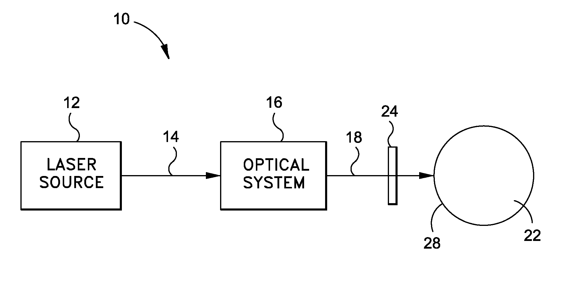
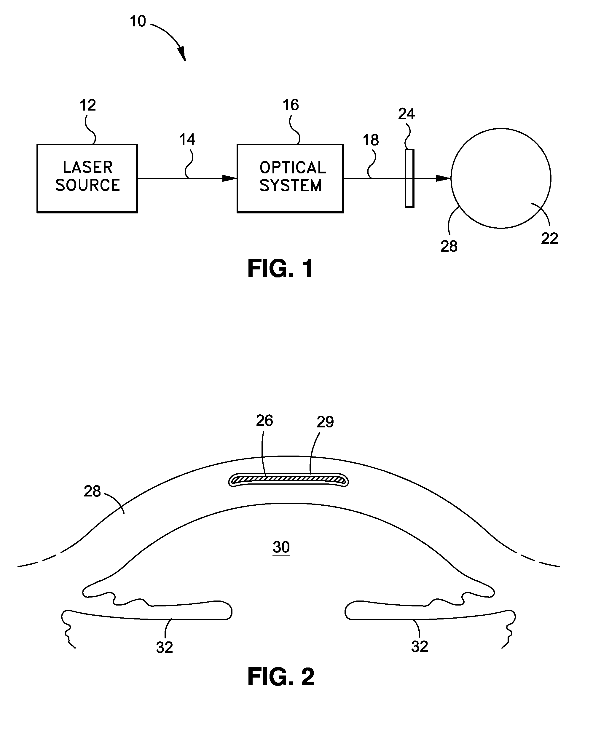
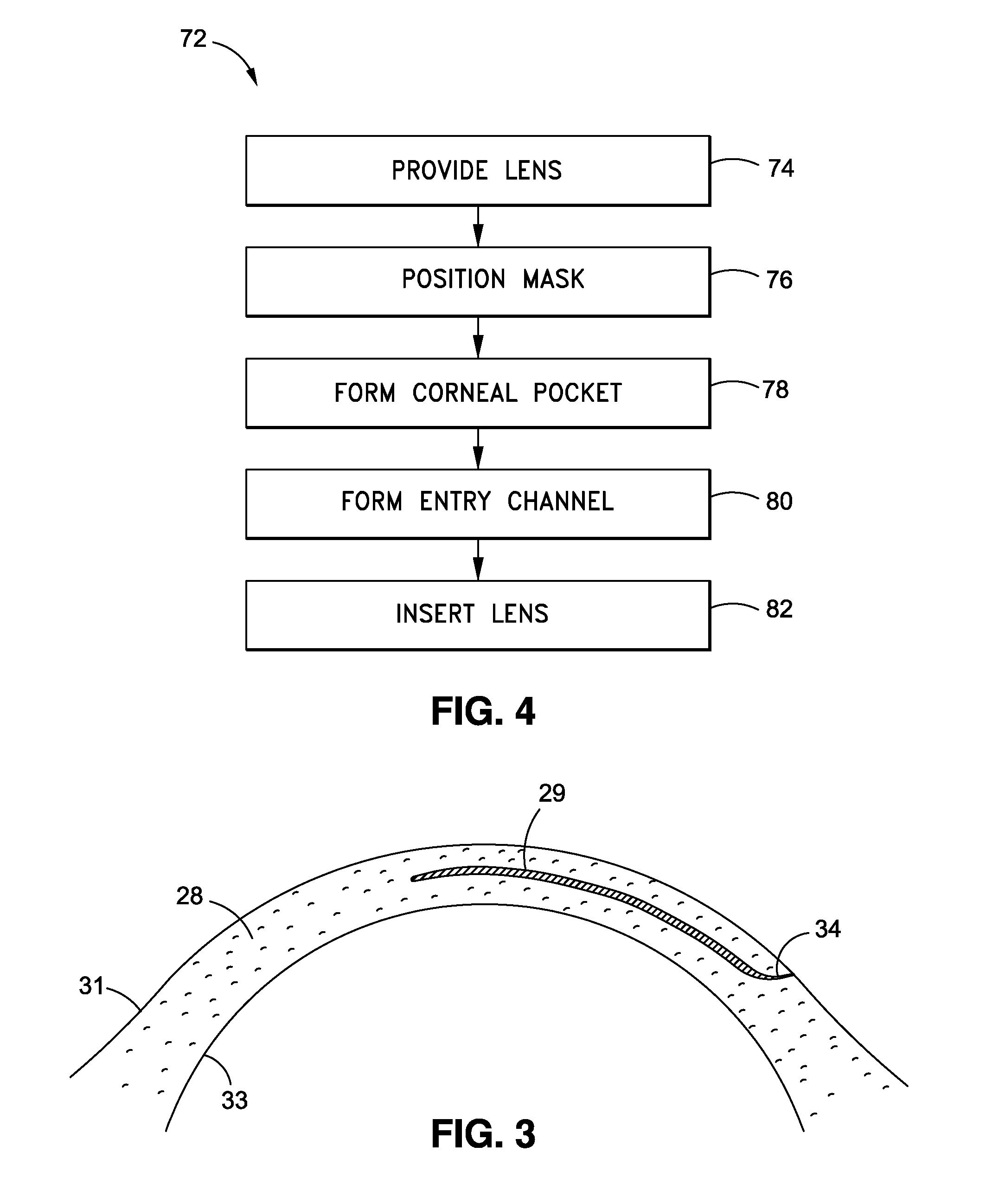
[0019]Broadly, the present invention relates to methods for correction of a visual deficiency of a patient. The present invention also relates to methods for using a mask to create an intracorneal pocket for receiving an intracorneal lens in a patient's eye. The present invention still further relates to a variety of mask configurations to create a variety of corneal pocket configurations.
[0020]In contrast to the prior art, some embodiments of the present invention use masks to insure that intracorneal pockets created by a laser conform to a desired shape. This enables the surgeon to accurately and quickly control the shape of the pocket without requiring costly and complicated programmable equipment. Also, in some embodiments of the present invention, a variety of different corneal pocket shapes may be created to further enhance the ease of insertion of a intracorneal lens of different shapes and sizes, and to maximize the surface of the cornea which is left intact, thereby facilitating healing. Other surgical procedures such as the creation of arcuate cuts on the cornea may also be made using the masks in accordance with some embodiments of the invention.
[0021]FIG. 1 shows a laser surgery apparatus 10 for laser surgery to create an intracorneal pocket in accordance with an embodiment of the invention. The laser surgery apparatus 10 may include a laser source 12 which preferably may be capable of generating and controlling a source beam 14 having a continuous train of laser pulses of substantially constant pulse duration and pulse energy. In one embodiment of the laser surgery apparatus 10, a source beam 14 may have a pulse duration of between approximately 500 picoseconds and 10 femptoseconds, a wavelength longer than 800 nanometers and pulse energy of approximately 6 μJ.
[0022]The laser surgery apparatus 10 further includes an optical system 16 for forming a shaped laser beam 18 and directing the shaped laser beam 18 toward and into the cornea 28 of an eye 22. Also shown in FIG. 1 is a mask 24 which is used to control the area of the cornea that is exposed to the laser beam 18 as described in more detail below.
[0023]FIG. 2 is a sectional view of the anterior portion of the eye 22 having an intracorneal lens 26 disposed therein, according to an embodiment of the invention. In the embodiment of the invention shown in FIG. 2, intracorneal lens 26 may be disposed within a cornea 28 of the eye 22, which may partially enclose the anterior chamber 30 of the eye 22. Also shown in FIG. 2 is an iris 32. In accordance with an embodiment of the invention, lens 26 may be inserted within cornea 28 following formation of a corneal pocket 29, which may be formed using a laser surgery apparatus 10 as shown in FIG. 1.
[0024]Intracorneal lens 26 is not restricted to the configuration shown in the drawings, but may have various shapes, such as circular or oval. In some embodiments, intracorneal lens 26 may have a doughnut-like configuration. The size and shape of intracorneal lens 26 may, in some cases, determine the size and shape of the corneal pocket. Various embodiment of such cornea pockets are described below and shown in FIGS. 6A-6F.
[0025]The intracorneal lens 26 preferably may be formed of a biocompatible material that permits sufficient gas diffusion to allow adequate oxygenation of internal eye tissues. Such materials may include silicone, hydrogels, urethanes or acrylics. It also may be desirable that the lens be made of a hydrophilic material which swells somewhat when hydrated. Such materials, for example, hydrogels, are well known and are used in some present contact lenses.
[0026]The optical characteristics of intracorneal lens 26 may be selected for correcting various visual deficiencies, including without limitation: myopia (short sightedness), hypermetropia (long sightedness), presbyopia and astigmatis. As an example, intracorneal lens 26 may have a diopter power or value in the range of from +15 to −30. Intracorneal lens 26 may be customized for a particular patient to provide optical characteristics to correct a specific visual defect of a patient. Intracorneal lens 26 may be multi-focal, may be provided as an off-the-shelf unit with pre-determined optical characteristics and may have zones with optical power and zones without optical power. It is to be understood that the present invention is not limited to treatment of the aforementioned visual defects, and that treatment of other eye conditions is also within the scope of the invention.
[0027]FIG. 3 shows a cross section of a cornea 28 having a corneal pocket 29 formed by a laser surgery apparatus 10 in accordance with one embodiment of the invention. Cornea 28 has an anterior surface 31 and a posterior surface 33. Corneal pocket 29 may be formed by photo ablation using laser beam 18 from a laser source 12. The techniques for creating a corneal pocket are well known and are described in U.S. Pat. No. 7,101,364 to Bille and U.S. Patent Application Publication No. US 2003/0014042 A1 to Juhasz et al. The contents of both of these documents are incorporated by reference in their entirety.
[0028]The corneal pocket 29 may be formed with a thickness and shape that conforms to the surfaces of the intracorneal lens 26. For example, the interior surfaces of the corneal pocket 29 may be convex, concave, planar or irregular. The edges of the corneal pocket 29 may form an outline having various shapes depending on the desired outcome and the shape of the intracorneal lens 26. The mask 24 shown in FIG. 1 may prevent the laser beam 18 from ablating tissue beyond the boundaries of the desired shape. FIGS. 5A-5M show exemplary masks which may be used for this purpose. In particular, masks 36, 38, 40, 42, 44, 46, 80, 82, 84, 86, 88 and 90 may be made of a material that is opaque to the laser beam 18 from laser source 12. Each mask may have an open region 48, 50, 52, 54, 56, 58, 92, 94, 96, 98, 100 and 102 which may be transparent to the laser beam 18 from laser source 12. As shown in FIGS. 5G-5M are arcuate openings 103. Open regions 48, 50, 52, 54, 58, 92, 96, 98, 100 and 102 may include both straight portions and arced portions. Open regions 56 and 94 may include straight portions extending across most of the surface of the masks 44 and 82 respectively.
[0029]FIGS. 6A-6M show the resulting corneal pockets 60, 62, 64, 66, 68, 70, 72, 74, 76, 78, 79 and 81 that may be created by the laser beam 18 passing through open regions of the corresponding masks 36, 38, 40, 42, 44, 46, 80, 82, 84, 86, 88 and 90. Also shown in FIGS. 6G-6M are the arcuate cuts 104 that may be created as a result of the laser beam 18 passing through arcuate openings 103. The various configurations of corneal pockets shown in FIGS. 6A-6M may be adapted to be used with lenses of various shapes and sizes. The corneal pockets 60-81 as configured may also facilitate the insertion of the lens and minimize the size of the incision for improved post-surgical healing of the cornea.
[0030]All of the corneal pockets shown in FIGS. 6A-6M may include an entry channel 34 that may be cut into the cornea 28 after the corneal pocket 29 is formed. Entry channel 34 may permit the insertion of the intracorneal lens 26 into the corneal pocket 29.
[0031]FIG. 4 schematically represents a series of steps involved in a process 72 for creating a corneal pocket and inserting a lens in the cornea of a patient, according to one embodiment of the invention. The process 72 may begin with the step 74 of providing an intracorneal lens 26. The intracorneal lens 26 may or may not have optical power depending on the purpose of the intracorneal lens 26. In step 76 a mask 24 may be positioned in front of the cornea 28. Mask 24 may have one of the configurations shown in FIG. 5A-F, or may have a different configuration. In step 78 a corneal pocket 29 may be formed. This may be done using the laser surgery apparatus 10 shown in FIG. 1. In particular, a laser source 12 being controlled by an optical system 16 may be used to focus a laser beam 18 within the corneal tissue. The laser beam 18 will ablate a region of the cornea tissue in the area of the focus of the laser beam 18. The focus of the laser beam 18 may then be moved laterally by hand to cut a layer of corneal tissue. While the focus of the laser beam 18 is being moved laterally, it may be maintained a fixed depth within the cornea using known laser surgical techniques. The focus of the laser beam 18 may be easily, quickly and accurately moved laterally by hand within the confines of the mask open region without the risk of cutting outside the desired area defined by the mask. In this way, the masks shown in FIGS. 5A-5M may be used to create the corneal pockets shown in FIGS. 6A-6M.
[0032]The thickness of the corneal pocket created using the above techniques will be about the size of the diameter of the laser beam 18 focal point. In some cases, depending on the thickness and shape of the intracorneal lens 26, additional tissue may be ablated at different depths within the cornea 28.
[0033]In step 80 an entry channel 34 may be formed. This may be accomplished using the laser source 12 or may be formed using a conventional scalpel. Entry channel 34 may provide a means for insertion of the intracorneal lens 26 and also will allow the release of gasses created by laser ablation when the intracorneal pocket 29 is formed.
[0034]The intracorneal lens 26 may then be inserted into the intracorneal pocket 29 in step 82. Step 82 may further involve temporarily deforming the intracorneal lens 26 before it is introduced into the cornea 28. The intracorneal lens 26 may be deformed by rolling, folding, and the like. The intracorneal lens 26 may have prescribed memory characteristics that allow it to return to its original size and configuration after insertion into the cornea 28, while retaining its desired optical characteristics. The intracorneal lens 29 may be made of a hydrophilic material which swells when hydrated. The lens may be inserted fully hydrated to elastically fit into a corneal pocket, or while at least partly dehydrated such that subsequent hydration helps secure the fit in the pocket.
[0035]As can be appreciated by those skilled in the art, the present invention may provide a method for correcting the vision of a patient with an intracorneal lens 26 that may be easily inserted into a corneal pocket 29. The corneal pocket 29 may be created using a laser source 12 or may be created using other forms of electromagnetic radiation. The creation of the corneal pocket 29 is facilitated by the use of a mask 24 that prevents the laser beam 18 from ablating tissue outside the boundary of a desired shape. The mask 24 may also be used in other kinds of ophthalmic surgery requiring partial lamellar resection, including LASIK surgery. A variety of corneal pocket configurations may be used to accommodate various corneal lens shapes and sizes. Other surgical procedures, such as arcuate cuts, may also be made using the techniques of the invention.
[0036]It should be understood, of course, that the foregoing relates to exemplary embodiments of the invention and that modifications may be made without departing from the spirit and scope of the invention as set forth in the following claims.

PUM

no PUM

Description & Claims & Application Information

We can also present the details of the Description, Claims and Application information to help users get a comprehensive understanding of the technical details of the patent, such as background art, summary of invention, brief description of drawings, description of embodiments, and other original content. On the other hand, users can also determine the specific scope of protection of the technology through the list of claims; as well as understand the changes in the life cycle of the technology with the presentation of the patent timeline. Login to view more.
Why Eureka
Try Eureka