

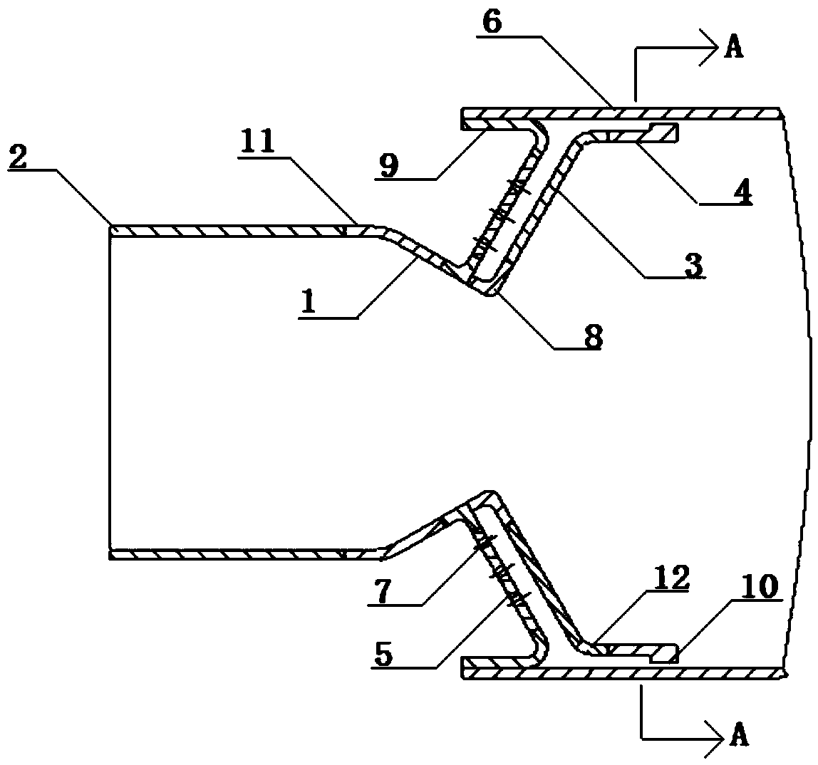
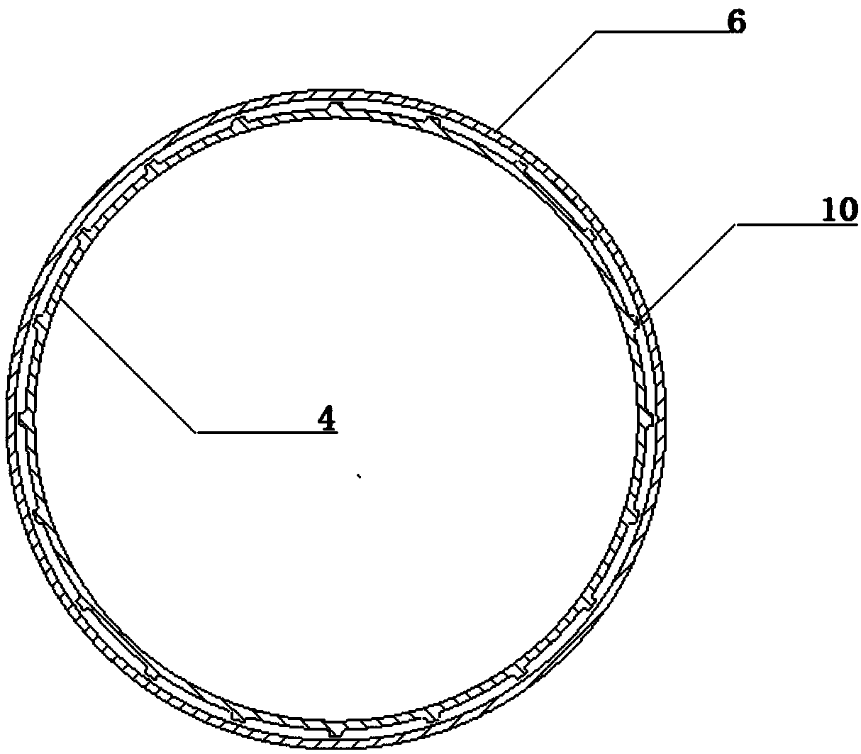
Combustion chamber head turning-connection structure
A combustion chamber and head technology, which is applied in the field of design of the transfer mechanism of the combustion chamber head, can solve the problems of limitations, inability to realize lean oil and low emissions of the combustion chamber, and tempering faults in the premixing section of the combustion chamber, so as to prevent The effect of being ablated
- Summary
- Abstract
- Description
- Claims
- Application Information
AI Technical Summary
Problems solved by technology
Method used
Image

Examples
Embodiment Construction
[0039] The application will be further described in detail below in conjunction with the accompanying drawings and embodiments. It should be understood that the specific embodiments described here are only used to explain the related application, not to limit the application. In addition, it should be noted that, for ease of description, only parts relevant to the present application are shown in the drawings.
[0040] It should be noted that, in the case of no conflict, the embodiments in the present application and the features in the embodiments can be combined with each other. The present application will be described in detail below with reference to the accompanying drawings and embodiments.
[0041] It should be noted that in the description of this application, the terms "center", "upper", "lower", "left", "right", "vertical", "horizontal", "inner", "outer", etc. The terms of the indicated direction or positional relationship are based on the direction or positional ...
PUM
 Abstract
Description
Claims
Application Information