
High-speed milling micro lubrication liquid supply nozzle structure and separation and recovery mechanism and system

A high-speed milling and micro-lubrication technology, used in metal processing machinery parts, metal processing equipment, maintenance and safety accessories, etc., can solve the problems of lubrication of parts not suitable for high-speed milling, cooling separation and collection device integration, etc., to achieve lubrication Good effect, reduce pollution, avoid splash effect

Active Publication Date: 2017-02-15
QINGDAO TECHNOLOGICAL UNIVERSITY
View PDF22 Cites 19 Cited by
  • Summary
  • Abstract
  • Description
  • Claims
  • Application Information

AI Technical Summary

Problems solved by technology

[0025] To sum up, the existing technology has studied the application of the minimum quantity lubrication system in machining, but the design scheme is not suitable for the lubrication and cooling of high-speed milling disk parts, as well as the separation and collection of oil, water, air and chips and the integration of collection devices

Method used


Image

  • High-speed milling micro lubrication liquid supply nozzle structure and separation and recovery mechanism and system
  • High-speed milling micro lubrication liquid supply nozzle structure and separation and recovery mechanism and system
  • High-speed milling micro lubrication liquid supply nozzle structure and separation and recovery mechanism and system

Examples


Embodiment Construction

[0077] The technical solutions in the embodiments of the present invention will be clearly and completely described below in conjunction with the drawings in the embodiments of the present invention.

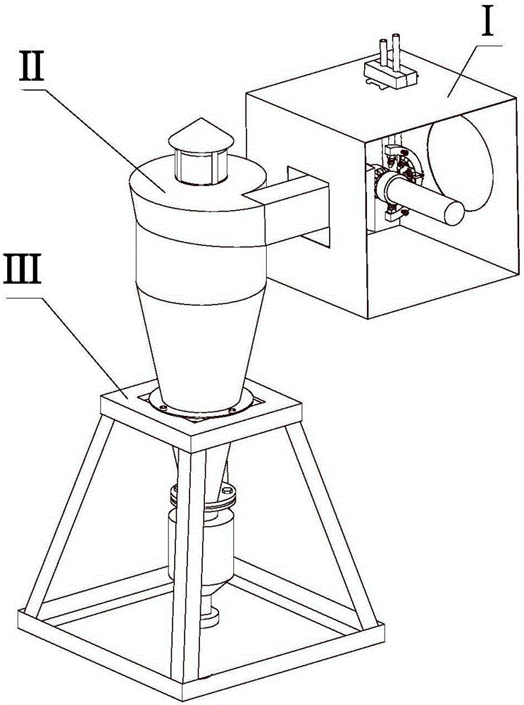
[0078] Such as Figure 1 to Figure 5 Shown is a structural diagram of a high-speed milling micro-lubrication liquid supply system.

[0079] Such as figure 1 As shown, a high-speed milling micro-lubrication liquid supply system is divided into three parts, consisting of high-speed milling processing part I, oil-water-air chip collection part II, and oil-water-gas chip separation support part III.

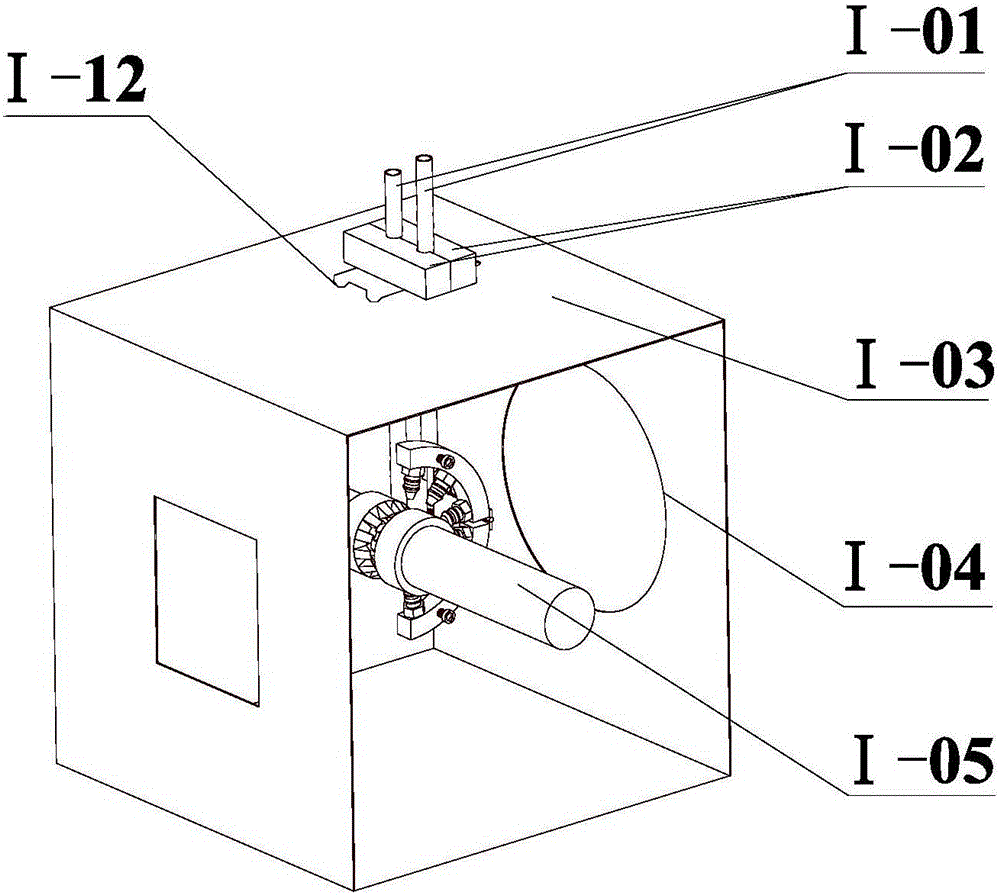
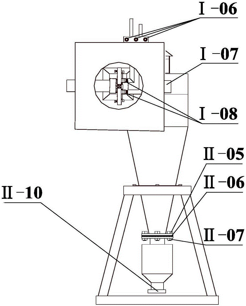
[0080] Such as Figure 2 to Figure 5 , Figure 13 , Figure 14 As shown, the delivery pipe I-01 is connected to the pipeline casing through the serpentine universal joint I-08, and the two pipeline casings can form a semicircle, and are arranged up and down around the milling cutter. The nozzle is placed in the contact area between the workpiece and the high-speed milling cutter, ...


PUM


Abstract

The invention discloses a high-speed milling micro lubrication liquid supply nozzle structure and a separation and recovery mechanism and a system. The structure comprises at least two nozzle bodies; one ends of the nozzle bodies are connected with a pipeline shell, and the other ends of the nozzle bodies are spraying heads; mixing channels formed by internals of hollow pipes are arranged in the nozzle bodies; one ends of the mixing channels are communicated with at least two pipelines; gas is introduced in the first pipeline; lubricating oil is introduced in the second pipeline; a gas pipeline communicated with the first pipeline and a lubricating oil pipeline communicated with the second pipeline are arranged in the pipeline shell; the gas pipeline and the lubricating oil pipeline both surround the center point of the pipeline shell; through setting of the pipeline shell, the lubrication and the cooling of milled parts are realized, and the lubricating effect is good; and the structure can effectively prevent splashing of chips and fog drips through setting of a box body, reduces the harm to environments and operators in the machining process, meanwhile, can effectively realize separation of a lubricating agent, the chips and the gas, and reduces environmental pollution.

Description

technical field [0001] The invention relates to the field of milling, in particular to a structure of a micro-lubrication liquid supply nozzle for high-speed milling, a separation and recovery mechanism and a system. Background technique [0002] Milling is a high-efficiency machining method that uses a rotating multi-blade tool to cut a workpiece. During milling, the rotation of the milling cutter is the main motion, and the linear or rotary motion of the milling cutter or workpiece along the coordinate direction is the feed motion, which is suitable for the processing of plane and groove workpieces. [0003] High-speed milling is a high-efficiency milling method that performs fast feed speed with small amount of chips, but the metal removal rate is higher than that of deep milling, thereby prolonging tool life and reducing non-processing time. Its application is especially suitable for modern production with rapid response features. [0004] At present, a large amount of...

Claims


Application Information

Patent Timeline
Patent Type & Authority Applications(China)
IPC IPC(8): B23Q11/10
CPCB23Q11/1069B23Q11/1076
Inventor 郭树明李长河卢秉恒曹华军张彦彬杨敏张乃庆吴启东
Owner QINGDAO TECHNOLOGICAL UNIVERSITY
Learn More