
Punch for high-vacuum die casting and lubrication device for punch

A high-vacuum and punch technology, which is applied in the field of lubricating devices and vacuum die-casting punches, can solve the problems of poor sealing performance of ordinary injection punches, inability to adapt to high-vacuum die-casting, and pollute aluminum liquid, etc., to increase effective cooling area, reduce the frequency of punch replacement, good lubrication and cooling effect

Active Publication Date: 2014-05-28
GUANGDONG HONGTU TECHNOLOGY (HOLDINGS) CO LTD +1
View PDF5 Cites 9 Cited by
  • Summary
  • Abstract
  • Description
  • Claims
  • Application Information

AI Technical Summary

Problems solved by technology

In high vacuum die-casting, when the vacuum system evacuates the pressure chamber and mold cavity, external air can enter the pressure chamber and mold cavity through this gap, resulting in air hole defects
Therefore, ordinary injection punches have poor sealing performance and cannot meet the requirements of high vacuum die casting
In addition, in order to reduce the friction between the punch and the pressure chamber and prolong the service life of the punch, in the normal production process, lubrication is required between the pressure chamber and the punch. It is easy to produce organic volatiles, pollute the aluminum liquid and enter the cavity to produce pore defects

Method used


Image

  • Punch for high-vacuum die casting and lubrication device for punch
  • Punch for high-vacuum die casting and lubrication device for punch
  • Punch for high-vacuum die casting and lubrication device for punch

Examples


Embodiment Construction

[0055] In order to make the object, technical solution and advantages of the present invention clearer, the present invention will be further described in detail below in conjunction with the accompanying drawings and embodiments. It should be understood that the specific embodiments described here are only used to explain the present invention, not to limit the present invention. In addition, the technical features involved in the various embodiments of the present invention described below can be combined with each other as long as they do not constitute a conflict with each other.

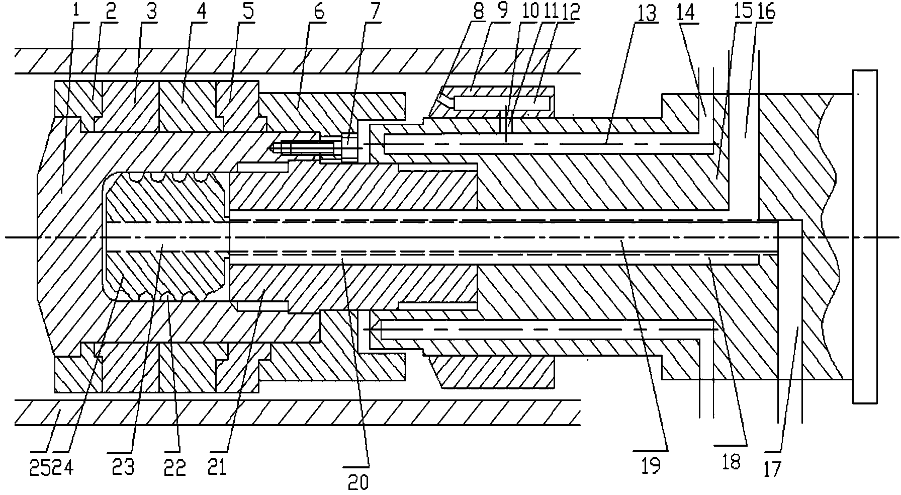
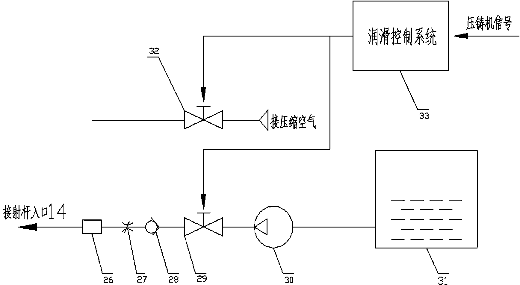
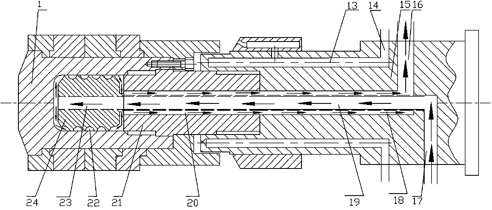
[0056] Such as figure 1 , 2 As shown, the device of the embodiment of the present invention includes a punch body 1, punch rings 2, 6, sealing rings 3, 4, 5, screws 7, distributor outlet 8, distributor 9, distributor annular groove 10, Shooting rod outer circumference surface 11, distributor flow channel 12, shooting rod lubricant flow channel 13, shooting rod lubricant inlet 14, shooting rod ...


PUM


Abstract

The invention discloses a punch for high-vacuum die casting. The punch for high-vacuum die casting comprises a punch body, an ejection rod provided with an axial through hole and a punch ejection rod threaded connecting piece provided with an axial center through hole, wherein an axial center through hole in a certain depth is formed in one end of the punch body and serves as a cooling chamber, the ejection rod is arranged coaxial with the punch body in an opposite mode, the other opposite end is connected with a driving component, the punch ejection rod threaded connecting piece is arranged between the punch body and the ejection rod, the two ends of the punch ejection rod threaded connecting piece are fixedly connected with the end of the punch body and the end of the ejection rod respectively, and a water cooling pipe used for providing cooling water penetrates through the center through hole of the ejection rod and the center through hole of the punch ejection rod threaded connecting piece and is communicated with a center through whole of a threaded water groove piece. The invention further discloses a lubrication device for the punch. According to the lubrication device, the punch and a pressure chamber can be effectively sealed, and the punch can be well lubricated and cooled through spraying lubrication of the ejection rod and a water cooling circulation system, so that the service life of the punch and the service life of the pressure chamber are prolonged, the frequency for replacement of punches is reduced, and the production efficiency is improved.

Description

technical field [0001] The invention relates to the technical field of die casting, in particular to a punch for vacuum die casting and a lubricating device for the punch. Background technique [0002] Die casting, referred to as die casting, is to pour molten or semi-molten metal into the pressure chamber of the die casting machine, and the punch presses the metal into the cavity of the mold at a very high speed, and then the molten metal is rapidly solidified under high pressure. A casting method. Die-casting has a short forming cycle and high production efficiency, but due to the fast filling speed of molten metal, the gas in the mold cavity cannot be removed in time, resulting in inevitable pores inside the casting, which greatly affects the mechanical properties and internal quality of the casting, limiting The application fields of die castings. [0003] In order to avoid pore defects inside the casting, it is an effective solution to pump out the gas in the mold cav...

Claims


Application Information

Patent Timeline
Patent Type & Authority Applications(China)
IPC IPC(8): B22D17/30B22D17/14
Inventor 万里朱鹏黄志垣安肇勇徐世裕余亮陈大贤吴树森
Owner GUANGDONG HONGTU TECHNOLOGY (HOLDINGS) CO LTD
Learn More