Cooking appliance with automatic exhaust function

A cooking utensil and automatic exhaust technology, applied in the direction of pressure cooker, etc., can solve the problems of large resistance, affecting sealing, eccentricity of weight, etc., and achieve the effect of simple structure, avoiding potential safety hazards, and convenient operation

Inactive Publication Date: 2014-11-12
GREE ELECTRIC APPLIANCES INC
View PDF7 Cites 20 Cited by
  • Summary
  • Abstract
  • Description
  • Claims
  • Application Information

AI Technical Summary

Problems solved by technology

Then realize the rotation of the weight, so that the weight moves up and away from the exhaust pipe, so as to achieve the purpose of exhausting, but this structure has relatively more movement, and the resistance is too large when used, resulting in poor exhaust effect, and it is necessary to realize automatic exhaust. To prevent the danger of burns caused by manual operation, it is necessary to increase the electric device and change the structure of the weight at the same time. After the structure of the weight is changed, it is easy to cause the weight to be eccentric, and long-term use will affect the sealing.

Method used


Image

  • Cooking appliance with automatic exhaust function
  • Cooking appliance with automatic exhaust function
  • Cooking appliance with automatic exhaust function

Examples


Embodiment approach 1

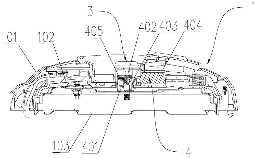
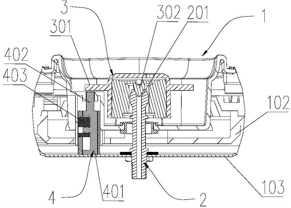
[0038] like Figure 1 to Figure 5 As shown, in this embodiment, the application provides a cooking utensil with an automatic exhaust function, including a cover body 1, an exhaust pipe 2 arranged on the cover body 1, and an exhaust pipe sleeved on the exhaust pipe 2 The exhaust port 201 is used to seal the exhaust port 201 or unseal the pressure limiting valve 3, which also includes a pressure limiting valve driving device 4 and a control device (not shown), and the pressure limiting valve driving device 4 can be used in Under the control of the control device, the pressure limiting valve 3 is driven to move upwards and release the seal on the exhaust port 201 .

[0039] In this application, through the cooperation of the control device and the pressure limiting valve driving device 4, the sealing of the pressure limiting valve 3 to the exhaust port 201 can be released, and the exhaust of the electric pressure cooker can be realized. It avoids the potential safety hazard caus...

Embodiment approach 2

[0052] like Image 6 As shown, in this embodiment, the present application provides another structural form of the pressure limiting valve driving device. In this embodiment, the pressure limiting valve driving device includes a rack 406, a gear 407 that cooperates with the rack 406, and a motor 408 that drives the gear 407 to rotate. The rack 406 moves linearly under the drive of the gear 407 and moves toward the pressure limiting valve arm. 301 apply force.

[0053] Specifically, the rack 406 is slidably arranged on the cover 1, and the gear 407 drives the rack 406 engaged with it to move up and down along the cover 1 under the drive of the forward and reverse rotation of the rotor of the motor 408, and during the upward movement An upward force can be applied to the pressure limiting valve arm 301 , and then the pressure limiting valve 3 releases the seal on the exhaust port 201 to perform exhaust.

[0054] In this embodiment, except that the driving device of the pressur...

Embodiment approach 3

[0056] like Figure 7 As shown, in this embodiment, the present application provides another structural form of the pressure limiting valve driving device. The pressure limiting valve driving device includes a driving motor 409 , and a cam 410 driven by the driving motor 409 to rotate and apply force to the pressure limiting valve arm 301 .

[0057] Specifically, the driving motor 409 is arranged on the cover body 1, and the cam 410 is arranged under the pressure limiting valve arm 301. When the cam 410 rotates under the drive of the driving motor 409, the flange of the cam 410 and the pressure limiting valve arm When 301 is in contact, an upward force can be applied to the pressure limiting valve arm 301, thereby causing the pressure limiting valve 3 to release the seal on the exhaust port 201 for exhausting. When the valve arm 301 is not in contact, the pressure limiting valve arm 301 is no longer subject to the upward force exerted by the flange, and under the action of gr...


PUM


Abstract

The invention relates to the technical field of cooking appliances and in particular relates to a cooking appliance with an automatic exhaust function. The cooking appliance with the automatic exhaust function comprises a cover, an exhaust pipe arranged on the cover, a pressure-limiting valve which sleeves the exhaust port of the exhaust pipe and is used for sealing or unsealing the exhaust port, and a pressure-limiting valve driving device and a control device; the pressure-limiting valve driving device is capable of driving the pressure-limiting valve to move upwards and unseal the export port under the control of the control device. The cooking appliance with the automatic exhaust function is capable of stopping the pressure-limiting valve from sealing the exhaust port by match of the control device and the pressure-limiting valve driving device and thus realizing exhaust of the electric pressure cooker. Potential safety hazards caused by directly operating the pressure-limiting valve by the hands are avoided; meanwhile, the device for realizing automatic exhaust of the electric pressure cooker is simple in structure and convenient to operate.

Description

technical field [0001] The invention relates to the technical field of cooking utensils, in particular to a cooking utensil with an automatic exhaust function. Background technique [0002] Since the electric pressure cooker is in a high-pressure environment during cooking, the user needs to wait for the high-temperature steam in the pot to completely liquefy into water after the electric heating device stops heating before opening the pot cover safely. Generally, the lid of the electric pressure cooker can only be opened after the electric pressure cooker stops heating and waits for a period of time. The exhaust of the existing electric pressure cooker mostly adopts a heavy hammer type pressure limiting valve. By manually rotating the heavy hammer, the heavy hammer moves upward and escapes from the exhaust pipe, thereby To achieve the purpose of exhaust, and then open the lid. [0003] Moreover, in the manual steam exhaust process, there may be a safety problem that the hi...

Claims


Application Information

Patent Timeline
Patent Type & Authority Applications(China)
IPC IPC(8): A47J27/08A47J27/09
Inventor 赖达英韦坤生马日春
Owner GREE ELECTRIC APPLIANCES INC
Why Eureka
Try Eureka