

Self-contained regulating valve, and compression type refrigerating machine having the same
An automatic regulating valve and refrigerant technology, which is applied in the direction of irreversible cycle compressors, refrigerators, compressors, etc., can solve the problems of increasing the manufacturing cost of turbo refrigerators, large and expensive intermediate suction valves, etc., and achieve simple structure , Avoid stagnation, low price effect
- Summary
- Abstract
- Description
- Claims
- Application Information
AI Technical Summary
Problems solved by technology
Method used
Image

Examples
no. 1 example
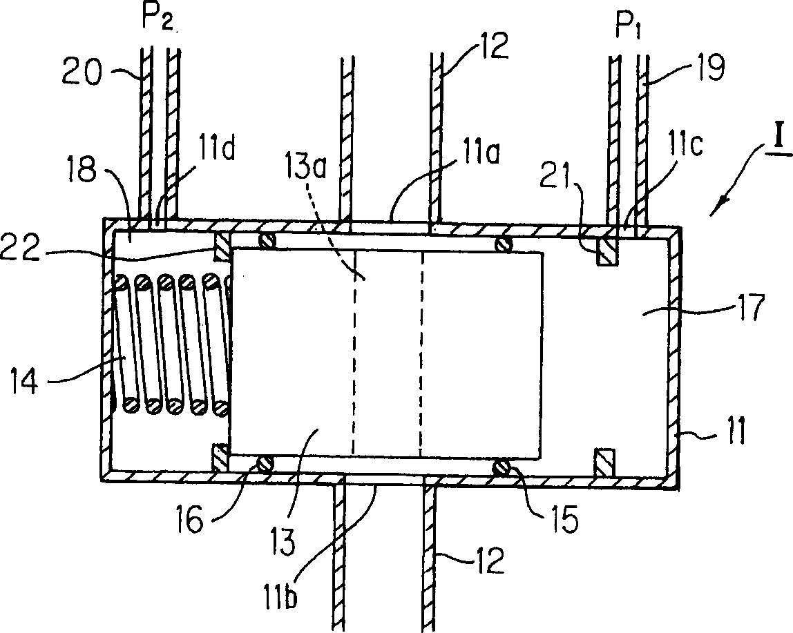
[0039] figure 1 It is a block diagram showing the automatic regulating valve of the first embodiment of the present invention. As shown in the figure, the valve body 11 of the automatic regulating valve 1 forming a cylindrical closed space has an inlet 11a and an outlet 11b formed at opposite positions in its middle portion for inflow and outflow of fluid. A spool 13 is accommodated in the interior space. The automatic regulating valve 1 is connected to pipelines 12 and 12 located at its upper and lower parts in the figure through an inlet 11a and an outlet 11b. The spool 13 has a through hole 13a for fluid passage opposite to the inlet 11a and the outlet 11b, and the spool 13 is slidable in the inner space of the valve body 11 in the axial direction in the figure left and right. A preload of a predetermined magnitude is applied to one end face of the spool 13 by a preload spring 14 . O-rings 15 , 16 are mounted on the outer peripheral surfaces of the right and left end po...
no. 2 example
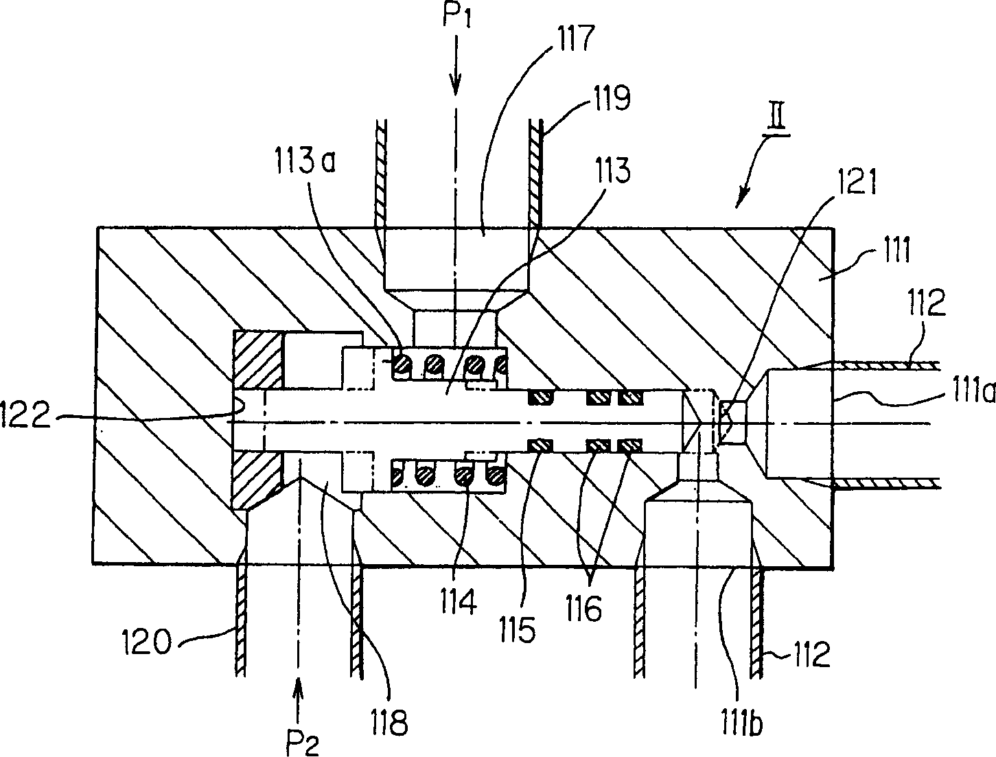
[0041] figure 2 It is a block diagram showing the automatic regulating valve of the second embodiment of the present invention. As shown in the figure, the automatic regulating valve II is designed in such a way that a pressure P introduced into a pressure transmission chamber 117 1 Acting on the flange portion 113 a, the pressure transmission chamber is a space formed between the tubular valve body 111 and the flange portion 113 a provided in the middle of the entire spool 113 . The spool 113 can move axially in the inner space of the valve body 111 . Another pressure transmission chamber 118 is a space formed between the valve body 111 and the spool 113 . Another pressure P 2 It acts on one end face of the spool 113 . A preload spring 114 is mounted on a portion of the spool 113 facing the pressure delivery chamber 117 to constantly press the spool 113 leftward in the drawing. Therefore, under normal conditions, the spring force of the preload spring 114 (the position ...
no. 3 example
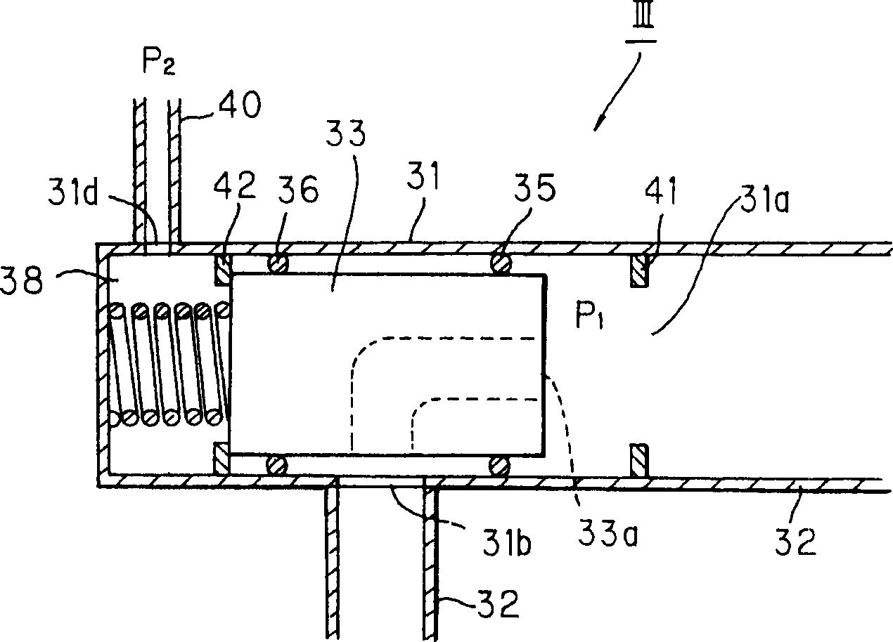
[0045] image 3 It is a block diagram showing the automatic regulating valve of the third embodiment of the present invention. The automatic regulating valve III according to this embodiment is effective when applied to the case where figure 1 A pressure P of the pressure delivery chamber 17 of the automatic regulating valve I shown 1 , can be obtained from the fluid flowing through line 12. This is because in this case the pressure of the controlled fluid is applied to one end face of the spool and this pressure of the fluid can be used as a pressure P 1 . Due to this characteristic, the structure of the automatic regulating valve III can be further simplified.
[0046] Such as image 3 Shown, automatic regulating valve III of the present invention and figure 1 Similar to the automatic regulating valve I shown in , it includes a valve body 31 , a spool 33 , a preload spring 34 , a pressure delivery chamber 38 and a pressure delivery line 40 . Among these components, ...
PUM
 Abstract
Description
Claims
Application Information