
Pictorial-based user interface management of computer hardware components

Inactive Publication Date: 2009-01-08
IBM CORP
View PDF16 Cites 41 Cited by
  • Summary
  • Abstract
  • Description
  • Claims
  • Application Information

AI Technical Summary

Benefits of technology

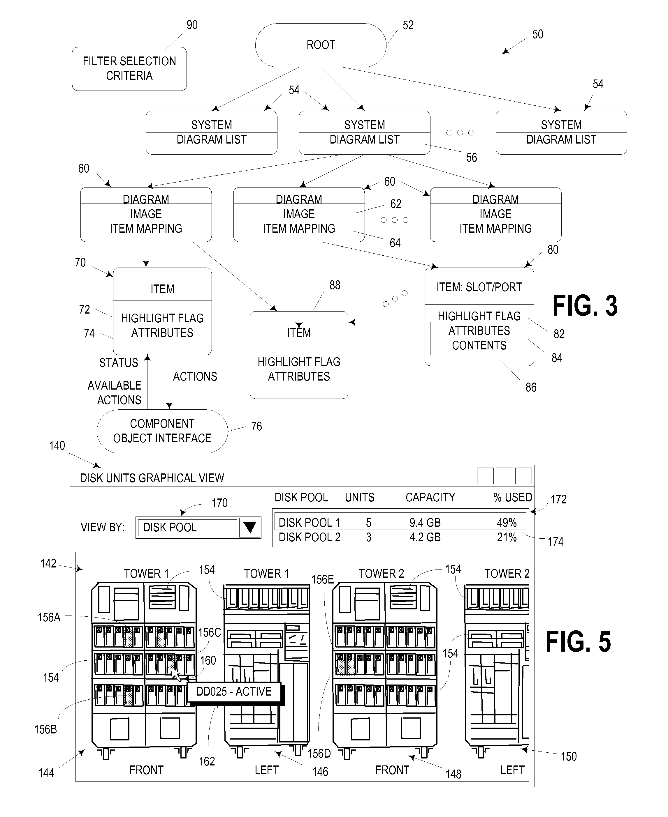
[0010]The invention addresses these and other problems associated with the prior art by providing an apparatus and program product in which a displayed pictorial representation that depicts the actual physical configuration of a plurality of hardware components in a physical computer system is utilized for facilitating the collective management of the underlying hardware components. In particular, within such a pictorial representation, a selected status is displayed for multiple of such hardware components. Such a configuration permits, for example, hardware components sharing common attributes or characteristics to be identified in an efficient and intuitive manner. In addition, such a configuration permits, for example, collective management operations to be performed on all selected hardware components, thus facilitating hardware management tasks where multiple components need to be configured in the same manner, and without requiring that each such component be configured via a separate operation.

Problems solved by technology

While GUI-based component managers offer substantial usability improvements over older, more cumbersome text-based component managers, most such GUI-based component managers have been found to be somewhat limited in the ability to inform a user of the underlying physical configuration of a hardware component within a computer system—specifically where in a computer a particular hardware component is physically located.
Looking at the actual computer, however, specific slots or ports may be difficult to locate, and a user may have difficulty in physically locating specific hardware components in the computer.
Moreover, this problem is significantly greater in complex multi-unit computer systems such as servers, midrange computers and mainframe computers, where the number of manageable hardware components can be overwhelming.
Management of the underlying hardware components is performed using the icons, and is limited to interaction via singular icons, and to hardware components located on a single computer.

Method used


Image

  • Pictorial-based user interface management of computer hardware components
  • Pictorial-based user interface management of computer hardware components
  • Pictorial-based user interface management of computer hardware components

Examples


Embodiment Construction

[0023]The embodiments described hereinafter may be used to enhance the ability of a user to effectively manage hardware components in a computer system through the use of a unique interactive pictorial display that pictorially represents the actual physical hardware configuration of one or more computers in a computer system. Consistent with the invention, such a pictorial display may be used to configure and manage hardware components on a local computer (i.e., on the same computer that is being managed) or on a remote computer (i.e., coupled to the managing computer over a network or other electronic interface).

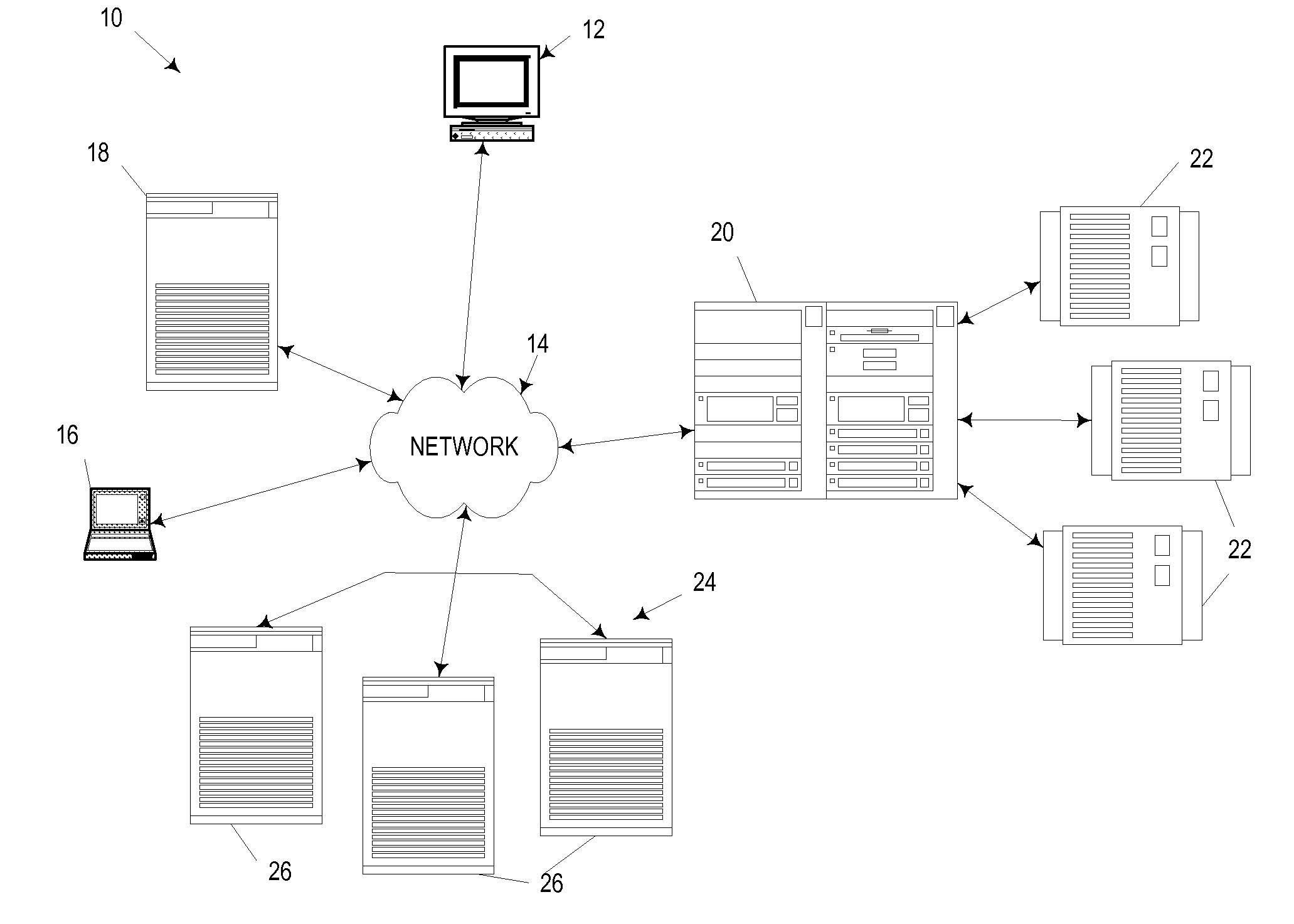
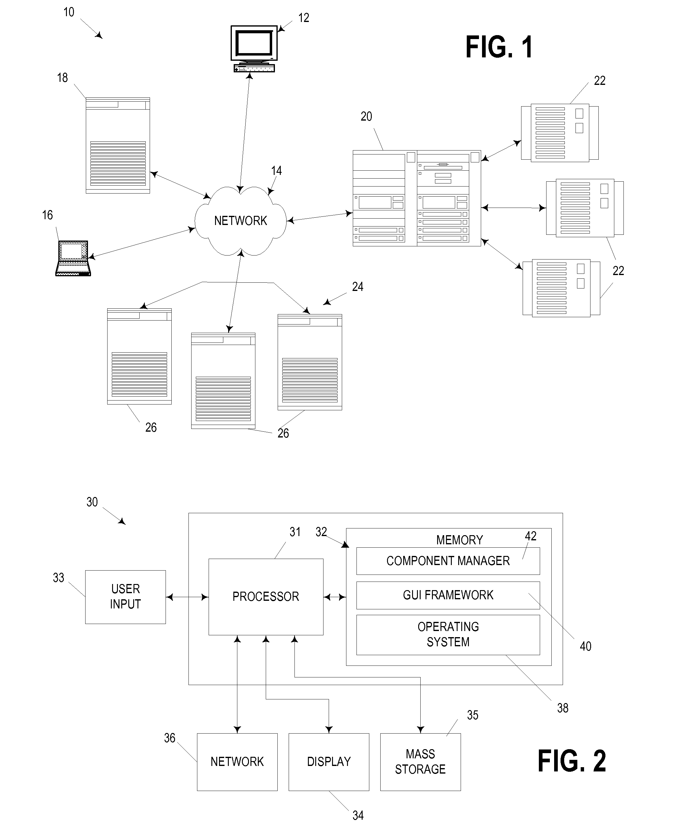
[0024]For example, FIG. 1 of the drawings, wherein like numbers denote like parts throughout the several views, illustrates a computer system 10 implementing pictorial-based computer hardware component management consistent with the invention. Computer system 10 includes a manager computer 12 coupled to a network generically represented at 14. Consistent with the invention,...


PUM


Abstract

An apparatus and program product utilize a displayed pictorial representation that depicts the actual physical configuration of a plurality of hardware components in a physical computer system to facilitate the collective management of the underlying hardware components. Typically, within such a pictorial representation, a selected status is displayed for multiple of such hardware components, thereby permitting hardware components sharing common attributes or characteristics to be identified in an efficient and intuitive manner, as well as to permit collective management operations to be performed on all selected hardware components. In addition, a pictorial representation may be dynamically generated to represent the physical configuration of a plurality of hardware components within a plurality of computers. In connection with such dynamic generation, the plurality of computers may be accessed to identify the plurality of hardware components that are resident in such computers.

Description

CROSS-REFERENCE TO RELATED APPLICATIONS[0001]This application is a continuation of U.S. patent application Ser. No. 09 / 659,258, filed on Sep. 11, 2000 by Gregory Richard Hintermeister et al. (ROC920000132US1), the entire disclosure of which is incorporated by reference herein.FIELD OF THE INVENTION[0002]The invention is generally related to computers and computer software. More specifically, the invention is generally related to user interfaces for use in managing computer hardware components.BACKGROUND OF THE INVENTION[0003]Graphical user interfaces (GUI's) have been used with great success to simplify and enhance user interaction with computers. In a GUI environment, a combination of text and graphical objects are displayed on a computer display, with a user able to interact with various objects predominantly through “pointing and clicking” with a user-manipulated pointer controlled by a mouse or similar device. GUI environments are often highly intuitive, as a user is able to per...

Claims


Application Information

Patent Timeline
IPC IPC(8): G06F3/00G06F11/32
CPCG06F11/328
Inventor HINTERMEISTER, GREGORY RICHARDLORY, BRADLEY JAMESMEAD, DAVID WALTERPEH, CHEEROYER, STEVEN EDWARD
Owner IBM CORP
Learn More