Multi-angle clamp

a multi-angle, clamping technology, applied in the field of multi-angle clamping, can solve the problems of limiting the selection of surgeons, orientating the pins of the two clamping devices, and requiring a large amount of skill for surgeons

Active Publication Date: 2009-01-15
ORTHEX LLC
View PDF5 Cites 98 Cited by
  • Summary
  • Abstract
  • Description
  • Claims
  • Application Information

AI Technical Summary

Benefits of technology

[0012]Accordingly, an object of the present invention is to provide a multi-angle clamp that can secure pins that are implanted in different planes and in a non-parallel manner while providing the ability to be secured to a rigid fixture.

Problems solved by technology

This need is often a result of a fracture which has occurred to the bone.
Additionally, during such a distracting procedure, the surgeon reorients the pins of the external fixation system over time to achieve the desired bone lengthening.
A common problem encountered by the surgeon is orientation of the pins of the two clamps.
This condition restricts the surgeon in the selection of the best insertion region on the bone for the pins.
In addition, it is very difficult and requires a high amount of skill for a surgeon to orient two or more pins exactly parallel to each other in a single plane.
However, such structures suffer from a variety of limitations.

Method used


Image

  • Multi-angle clamp
  • Multi-angle clamp
  • Multi-angle clamp

Examples


Embodiment Construction

[0033]For purposes of the description hereinafter, the terms “upper”, “lower”, “right”, “left”, “vertical”, “horizontal”, “top”, “bottom”, “lateral”, “longitudinal” and derivatives thereof shall relate to the invention as it is oriented in the drawing figures. However, it is to be understood that the invention may assume various alternative variations, except where expressly specified to the contrary. It is also to be understood that the specific devices illustrated in the attached drawings, and described in the following specification, are simply exemplary embodiments of the invention. Hence, specific dimensions and other physical characteristics related to the embodiments disclosed herein are not to be considered as limiting.

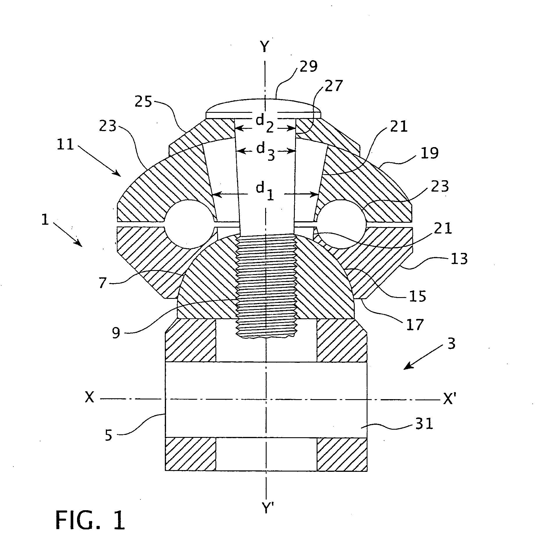
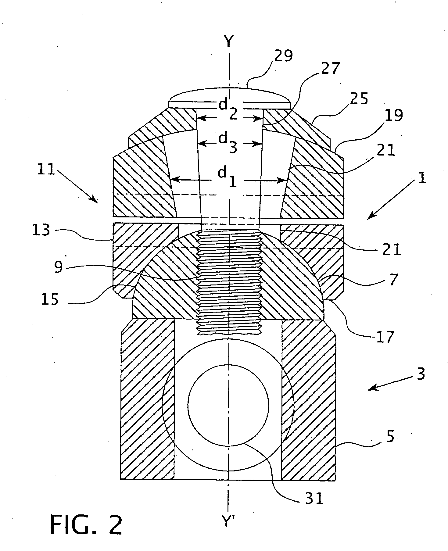
[0034]With reference to FIGS. 1 and 2, a multi-angle clamp, denoted generally as reference numeral 1, includes a body, denoted generally as reference numeral 3, having a bottom portion 5 and a top portion 7. Top portion 7 is shaped like a half sphere or semi-s...


PUM


Abstract

A clamp for an external fixation system includes a body having a bottom portion and semi-spherical top portion. The top portion has a threaded bore provided along a longitudinal axis: The clamp includes a clamp assembly having a base with a semi-spherical cavity and a lid positioned over the base to house at least one pin between the base and the lid. The base and the lid have a bore provided along a longitudinal axis thereof. A fastening member is provided that extends through the bore in the base and the lid of the clamp assembly and is secured within the threaded bore of the top portion of the body. The bores in the base and the lid have a diameter that is greater than the diameter of the fastening member.

Description

CROSS-REFERENCE TO RELATED APPLICATION[0001]This patent application claims priority to, and incorporates herein by reference, U.S. Provisional Application No. 60 / 937,391 filed Jun. 27, 2007.BACKGROUND OF THE INVENTION[0002]1. Field of the Invention[0003]The present invention relates, in general, to a multi-angle clamp, and more particularly, to a multi-angle clamp for use in an external fixation system for holding, distracting and compressing bone fragments adjacent to each other.[0004]2. Description of Related Art[0005]In various orthopedic surgical procedures, it is often necessary to secure two or more portions of bone in a relatively fixed relationship to each other. This need is often a result of a fracture which has occurred to the bone. To ensure that the bone can properly regenerate and fuse the fractures of the bone, it is important that the various bone fragments be positioned at the desired location during bone regeneration.[0006]External fixation systems have been develo...

Claims


Application Information

Patent Timeline
Patent Type & Authority Applications(United States)
IPC IPC(8): A61B17/00
CPCA61B17/62A61B17/6458A61B17/66A61B17/6475A61B17/6466
Inventor LAVI, ABRAHAM
Owner ORTHEX LLC
Why Eureka
Try Eureka