Stud retainer apparatus

a retainer and stud technology, applied in the direction of threaded fasteners, machine supports, ways, etc., can solve the problems of misalignment of conventional fastening assemblies with respect, incompatibility of conventional fastening assemblies with different types of studs, etc., and achieve the effect of maximizing surface engagemen

Active Publication Date: 2009-01-29
ILLINOIS TOOL WORKS INC
View PDF40 Cites 38 Cited by
  • Summary
  • Abstract
  • Description
  • Claims
  • Application Information

AI Technical Summary

Benefits of technology

[0008]The first and second engaging legs may inwardly curve about a central axis of said stud retainer. The inwardly-curved nature maximizes the surface engagement between the engaging legs and outer surfaces of the stud

Problems solved by technology

Conventional fastening assemblies are often not compatible with different types of studs.
Addit

Method used


Image

  • Stud retainer apparatus
  • Stud retainer apparatus
  • Stud retainer apparatus

Examples


Embodiment Construction

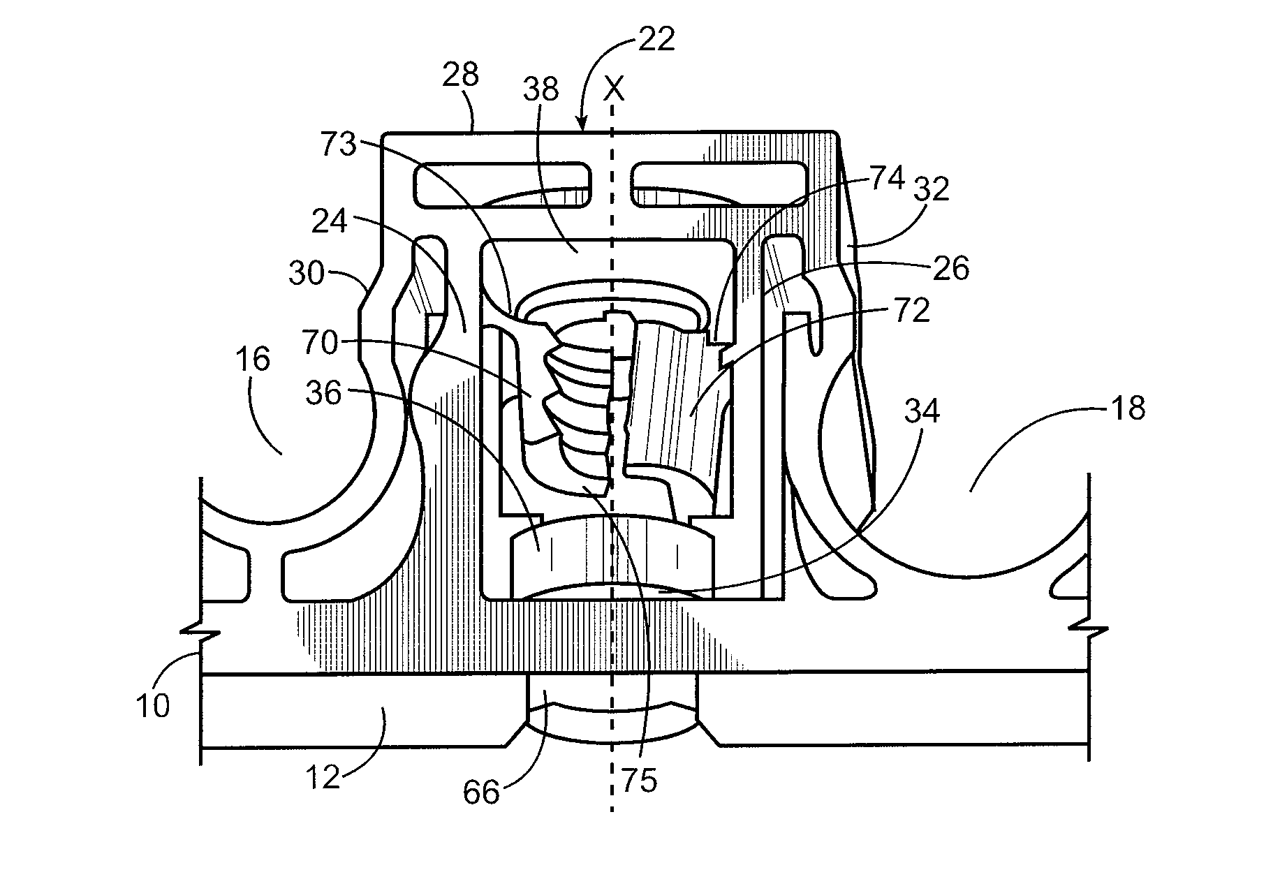
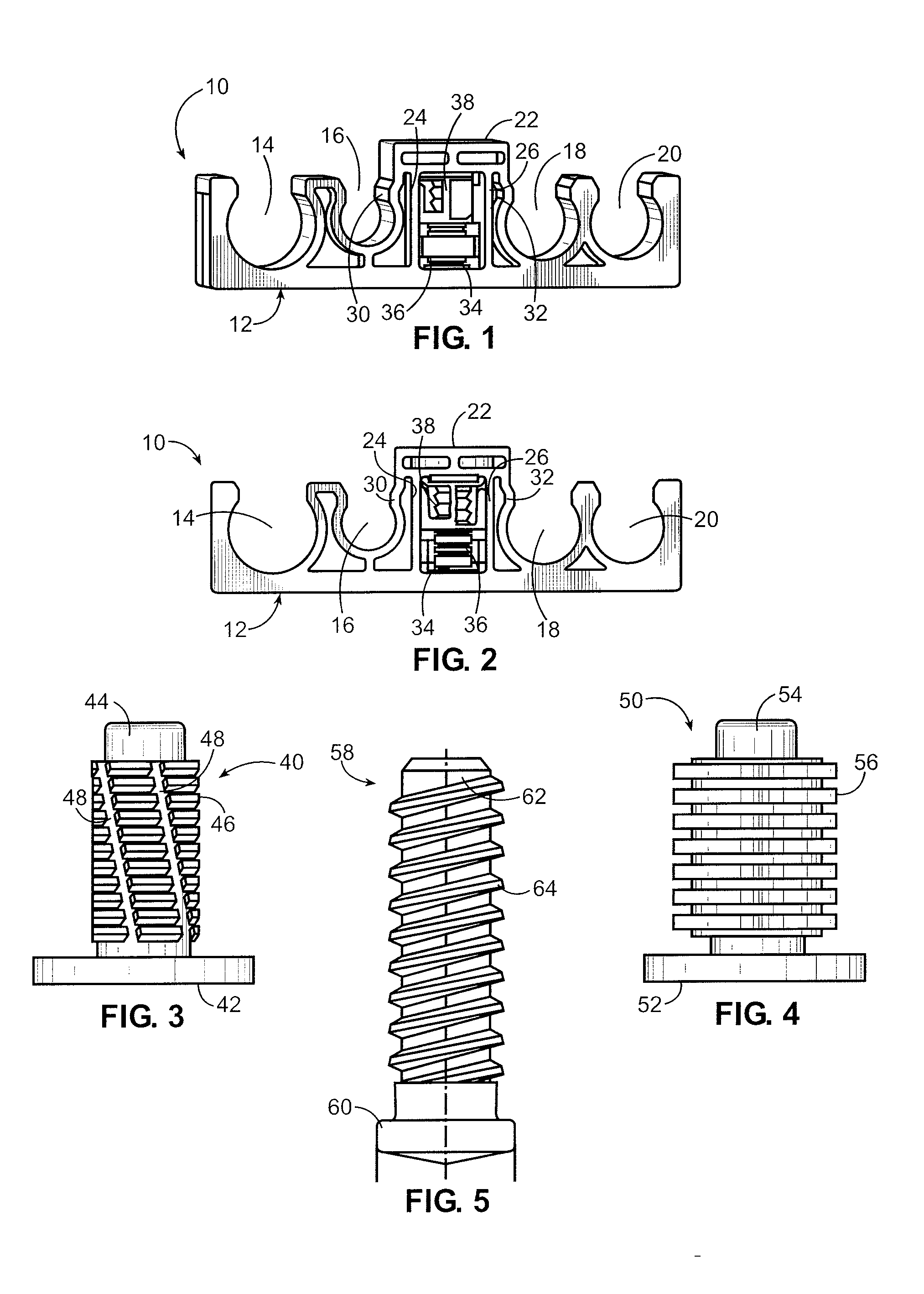
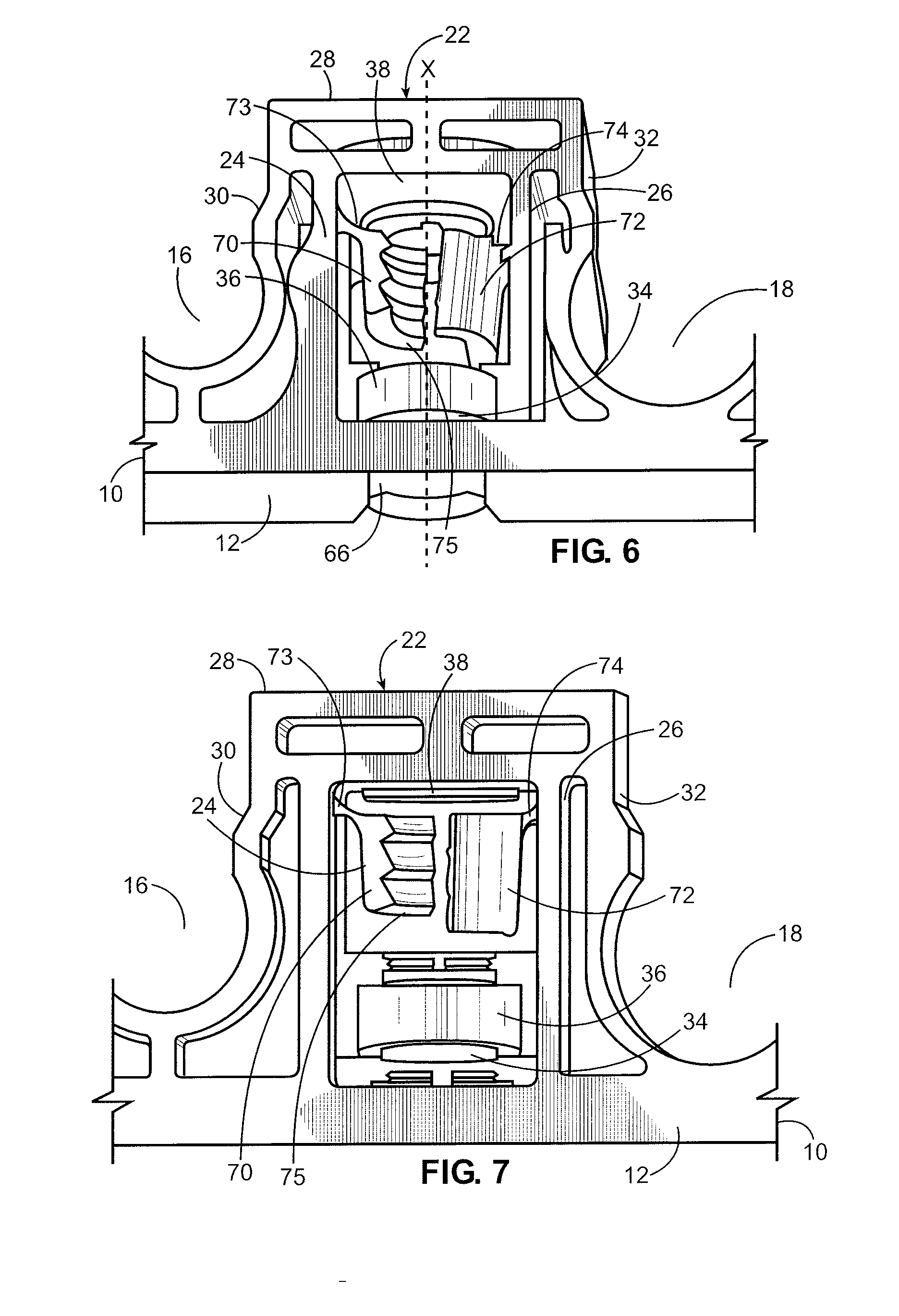
[0022]FIGS. 1 and 2 illustrate isometric and front views, respectively, of a connector assembly 10, according to an embodiment of the present invention. Referring to FIGS. 1 and 2, the connector assembly 10 includes a base 12 having a plurality of tube channels 14, 16, 18 and 20. Each tube channel 14, 16, 18 and 20 may be sized differently to accommodate different sized tubes (not shown). The tube channels 14, 16, 18 and 20 are configured to snapably and securely engage around outer circumferential surfaces of tubes. The connector assembly 10 may include more or less tube channels than those shown. Additionally, the connector assembly 10 may not include tube channels, but may include clamps, grooves, latches, claps, barbs or the like configured to securely retain other components, such as rails, beams or the like.

[0023]A stud retainer 22 extends from the base between the tube channels 16 and 18. As shown in FIGS. 1 and 2, the stud retainer 22 is generally centered on the base 12. Th...


PUM


Abstract

A connector assembly configured to secure at least one component to a structure may include a base, at least one member configured to receive and retain a portion of a component, and a stud retainer extending from the base. The stud retainer may include first and second engaging legs within a retaining chamber. The first and second engaging legs are configured to automatically align the stud retainer with respect to a stud that passes into the retaining chamber.

Description

RELATED APPLICATIONS[0001]This application relates to and claims priority benefits from U.S. Provisional Patent Application No. 60 / 961,616 entitled “Stud Retainer,” filed Jul. 23, 2007, which is hereby incorporated by reference in its entirety.FIELD OF THE INVENTION[0002]Embodiments of the present invention generally relate to a stud retainer apparatus, and more particularly to a self-centering / aligning stud retainer apparatus that may be easily secured to various types of studs.BACKGROUND OF THE INVENTION[0003]Various components, such as conduits and tubes, may be secured to surfaces, such as walls, ceilings or the like, through fastening assemblies. For example, a cylindrical tube may be secured to a wall through a fastening assembly having a tube channel that snapably secures around a portion of the tube. The fastening assembly itself may be secured to the wall through a stud that is received and retained by the fastening assembly.[0004]Conventional fastening assemblies are often...

Claims


Application Information

Patent Timeline
IPC IPC(8): F16B21/10
CPCF16B37/0857F16B5/0685F16L3/223
Inventor LUK, MELODIE S.
Owner ILLINOIS TOOL WORKS INC
Why Eureka
Try Eureka