Supercharge Your Innovation With Domain-Expert AI Agents!

Digital multimeter having case panel structure

a multimeter and case panel technology, applied in the field of digital multimeters, can solve problems such as various difficulties in the assembly process

Inactive Publication Date: 2009-02-19
JOHN FLUKE MFG CO INC
View PDF11 Cites 5 Cited by
  • Summary
  • Abstract
  • Description
  • Claims
  • Application Information

AI Technical Summary

Problems solved by technology

This has created various difficulties in the assembly process.

Method used


Image

  • Digital multimeter having case panel structure
  • Digital multimeter having case panel structure
  • Digital multimeter having case panel structure

Examples


Embodiment Construction

[0026]It is to be understood by one of ordinary skill in the art that the present discussion is a description of exemplary embodiments only, and is not intended as limiting the broader aspects of the present invention, which broader aspects are embodied in the exemplary constructions.

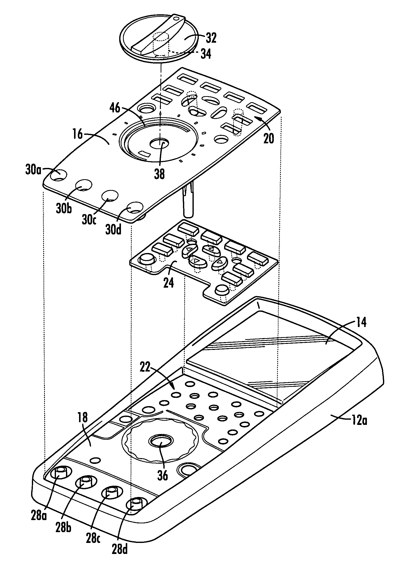
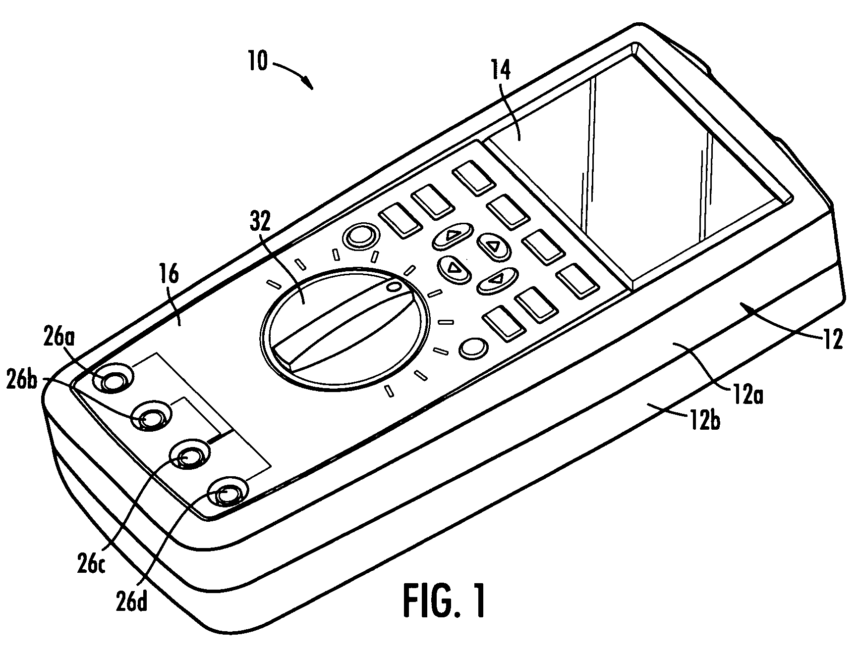
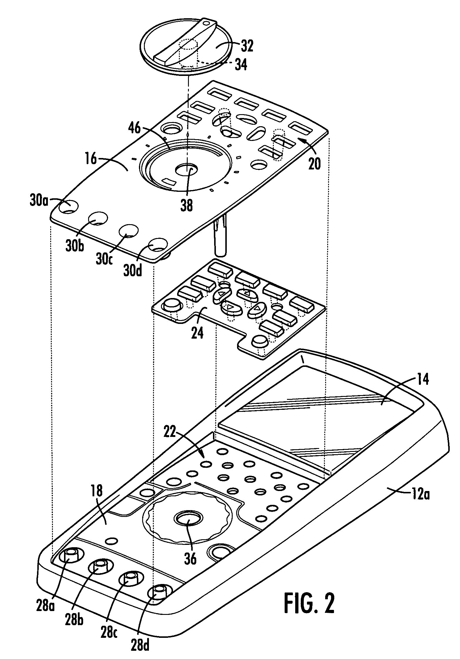
[0027]FIG. 1 illustrates a digital multimeter (DMM) 10 constructed in accordance with the present invention. Multimeter 10 comprises a housing in the form of a case 12 defining an interior cavity in which various internal components are located. In this embodiment, case 12 is preferably formed having top and bottom case members 12a and 12b which together define the interior cavity. Preferably, each of the case members 12a and 12b may be formed of a molded shell of high impact rigid plastic which is at least partially overmolded with a softer polymeric material. The softer material provides a desirable gripping surface. The molded shell of the bottom case member may be opaque, whereas embodiments are con...


PUM


Abstract

A multimeter includes a case defining an interior cavity in which components of the multimeter are located. The case has a top portion defining a plurality of first button apertures. A rotary selector knob is also provided for selecting a multimeter function. The multimeter further includes a separate front panel juxtaposed to the top portion of the case. The front panel has a plurality of second button apertures in respective register with at least some of the first button apertures. The top portion of the case may define a recess in which the front panel is received.

Description

BACKGROUND OF THE INVENTION[0001]The present invention relates generally to digital multimeters. More particularly, the invention relates to a digital multimeter having an improved structure for the front of the meter case.[0002]Digital multimeters (DMMs) function to measure a number of electrical parameters generally needed for service, troubleshooting and maintenance. Such parameters may include AC voltage and current, DC voltage and current, resistance and continuity. In some cases, a DMM may measure other parameters such as capacitance and temperature.[0003]A DMM will often be configured as a hand-held unit having a rotary selector knob by which the various functions are selected. A plurality of lead jacks are provided in the case (i.e., housing) of the unit for connection of test leads. The specific jack used may depend on the function that has been selected. An LCD display provides a reading of the tested parameter.[0004]A particular manufacturer may offer several different mo...

Claims


Application Information

Patent Timeline
Patent Type & Authority Applications(United States)
IPC IPC(8): G01R1/04
CPCH05K5/0017G01R1/04
Inventor WORONES, JEFFREY E.
Owner JOHN FLUKE MFG CO INC
Features
  • R&D
  • Intellectual Property
  • Life Sciences
  • Materials
  • Tech Scout
  • Unparalleled Data Quality
  • Higher Quality Content
  • 60% Fewer Hallucinations
Learn More