Plug Locking Assembly

Inactive Publication Date: 2009-02-19
PANDUIT
View PDF25 Cites 83 Cited by
  • Summary
  • Abstract
  • Description
  • Claims
  • Application Information

AI Technical Summary

Benefits of technology

[0011]The plug locking assembly may also incorporate various other features. A surface of at least one of the top and bottom arms may, for example, comprise a ramp. When a retaining wall is present, it may comprise a stop surface and/or an angled surface. When a cover is present, it may define two or more tool insertion slots for receiving a plug removal tool and include front end and re

Problems solved by technology

In some cases, the latch may be accidentally depressed or unauthorized users may tamper with the latch, resulting in unwanted removal of the plug from its associated jack.
These dual-plug installation

Method used


Image

  • Plug Locking Assembly
  • Plug Locking Assembly
  • Plug Locking Assembly

Examples


Embodiment Construction

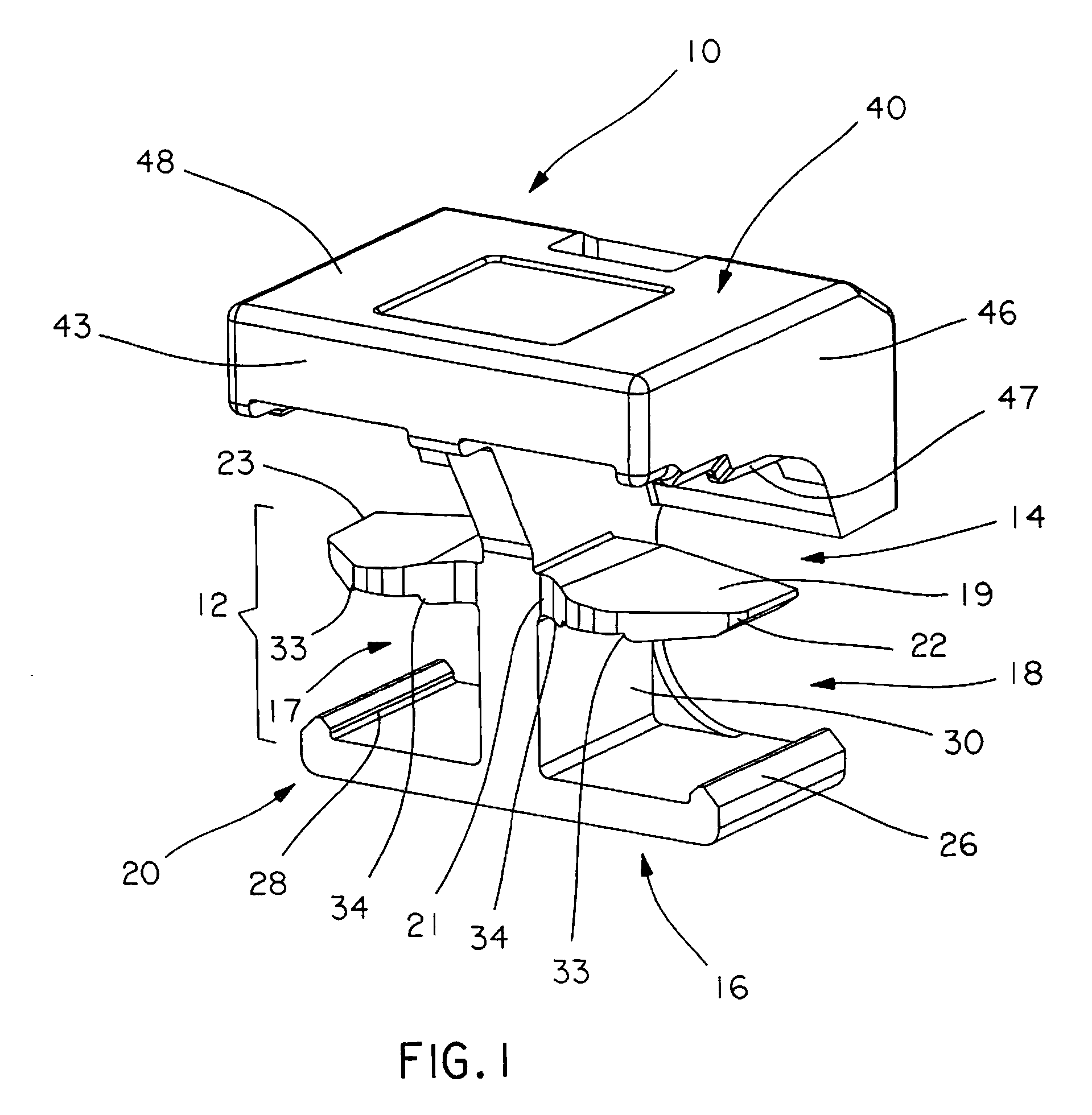
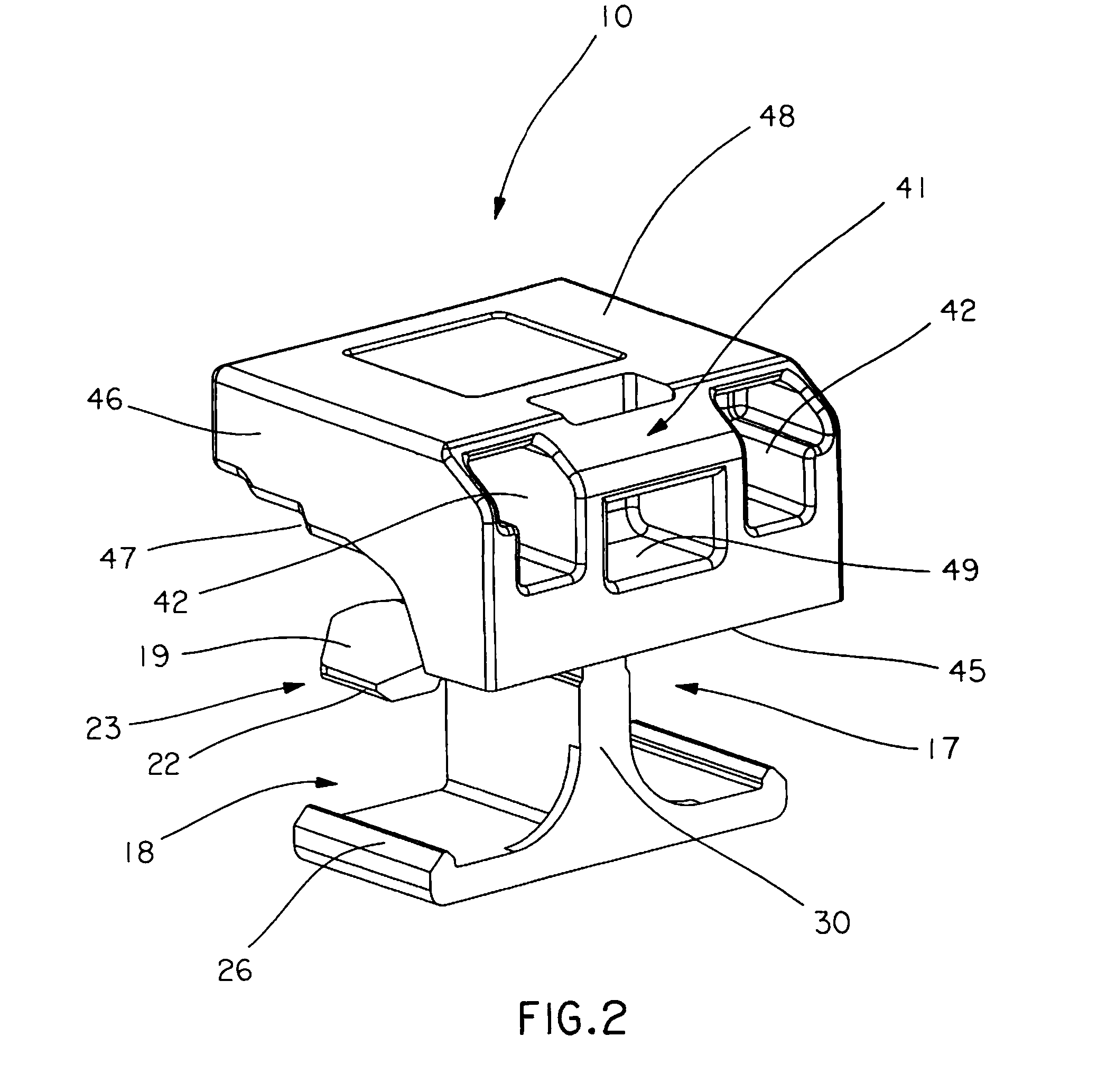
[0028]Referring now to FIGS. 1-3, plug locking assembly 10 comprises at least one plug holder 12, central wall 30 positioned between plug holder 12, and cover 40. Plug locking assembly 10 may be constructed through a one-piece trough injection by molding or machining processes well known to those skilled in the art, and may be constructed of plastic, metal, or any other moldable or machinable material.

[0029]Plug holders 12 each comprise opposing top arms 14 and opposing bottom arms 16, each extending transversely from central wall 30 and defining first open spaces 17 therebetween. As used herein, the term ‘transverse” means intersecting at an angle, including but not limited to a 90 degree angle. First open spaces 17 receive and hold plugs. Top arms 14 comprise first fixed ends 21 connected to central wall 30 and second free ends 23 spaced apart from first fixed ends 21 and may taper in width as they extend from first fixed ends 21 to second free ends 23. First fixed ends 21 are con...


PUM


Abstract

A plug locking assembly comprises at least one plug holder comprising opposing top and bottom arms, said top and bottom arms extending tranversely from a wall and defining open spaces therebetween, said open spaces for receiving and holding plugs. The plug holders are typically positioned adjacently to one another or in tandem and the configuration of the opposing top and bottom arms allows for side installation of plugs. The plug locking assembly may further comprise a cover overlying the plug holders.

Description

RELATED APPLICATION[0001]The present patent application claims priority under 35 U.S.C. §119(e) to U.S. Provisional Patent Application Ser. No. 60 / 956,491, which was filed Aug. 17, 2007, the full disclosure of which is incorporated herein by reference.FIELD OF THE INVENTION[0002]This invention relates to a plug locking assembly and, more particularly, to a plug locking assembly comprising securement features for holding a plurality of plugs in position adjacent to each other.BACKGROUND[0003]Telephones and computers are connected to telecommunications networks through the use of standardized modular connections. These modular connections often rely on the use of plugs secured within jacks. The plugs typically comprise a latch that engages with and secures the plug within the jack. The latch may be depressed to disengage the plug for easy removal from the jack, allowing easy disconnection of a device from a network without using tools. In some cases, the latch may be accidentally depr...

Claims


Application Information

Patent Timeline
IPC IPC(8): H01R13/62H01R13/627
CPCG02B6/3879H01R24/62H01R2201/06H01R13/6397G02B6/3893G02B6/3898
Inventor IRWIN, PHILLIP J.KUFFEL, GREGORY L.REID, ROBERT A.
Owner PANDUIT
Why Eureka
Try Eureka