Connection device for quickly connecting pneumatic hose

a technology of connecting device and pneumatic hose, which is applied in the direction of valve operating device/releasing device, valve type, coupling, etc., can solve the problems of easy wear and tear of the point “p”

Inactive Publication Date: 2009-02-26
CHANG JEN CHIH
View PDF4 Cites 11 Cited by
  • Summary
  • Abstract
  • Description
  • Claims
  • Application Information

AI Technical Summary

Benefits of technology

[0004]The present invention relates to a connecting device which comprises an inner tube with a plurality of elongate holes defined through a wall thereof and a plurality of oval-shaped beads are movably engaged with the elongate holes. Each of the elongate holes includes a long axis which is perpendicular to a longitudinal axis of the inner tube and a short axis which is parallel to the longitudinal axis of the inner tube. Each of the beads includes a long axis and a short axis. A part of each of the beads in the direction of the short axis protrudes beyond an inner surface of the inner tube. An outer tube is movably mounted to an outer surface of the inner tube and an inlet member is connected to a first end of the inner tube. A valve unit is movably located in the inner tube and includes a collar which movably contacts the inner surface of the inner tube and closes the elongate holes.
[0005]The present invention will become more obvious from the following description when taken in connection with the accompanying drawings which show, for purposes of illustration only, a preferred embodiment in accordance with the present invention.

Problems solved by technology

The point “P” is suffered by huge pressure and is easily worn out.

Method used


Image

  • Connection device for quickly connecting pneumatic hose
  • Connection device for quickly connecting pneumatic hose
  • Connection device for quickly connecting pneumatic hose

Examples


Embodiment Construction

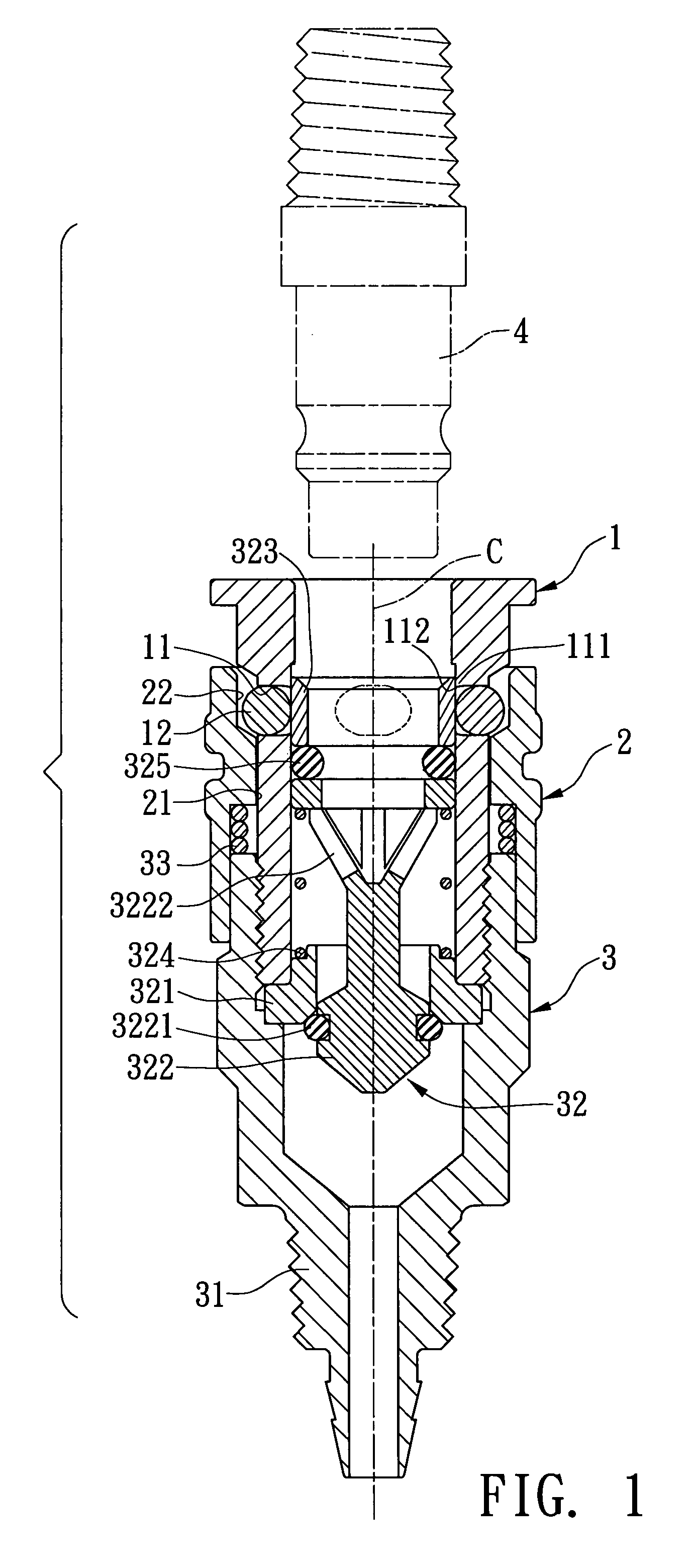
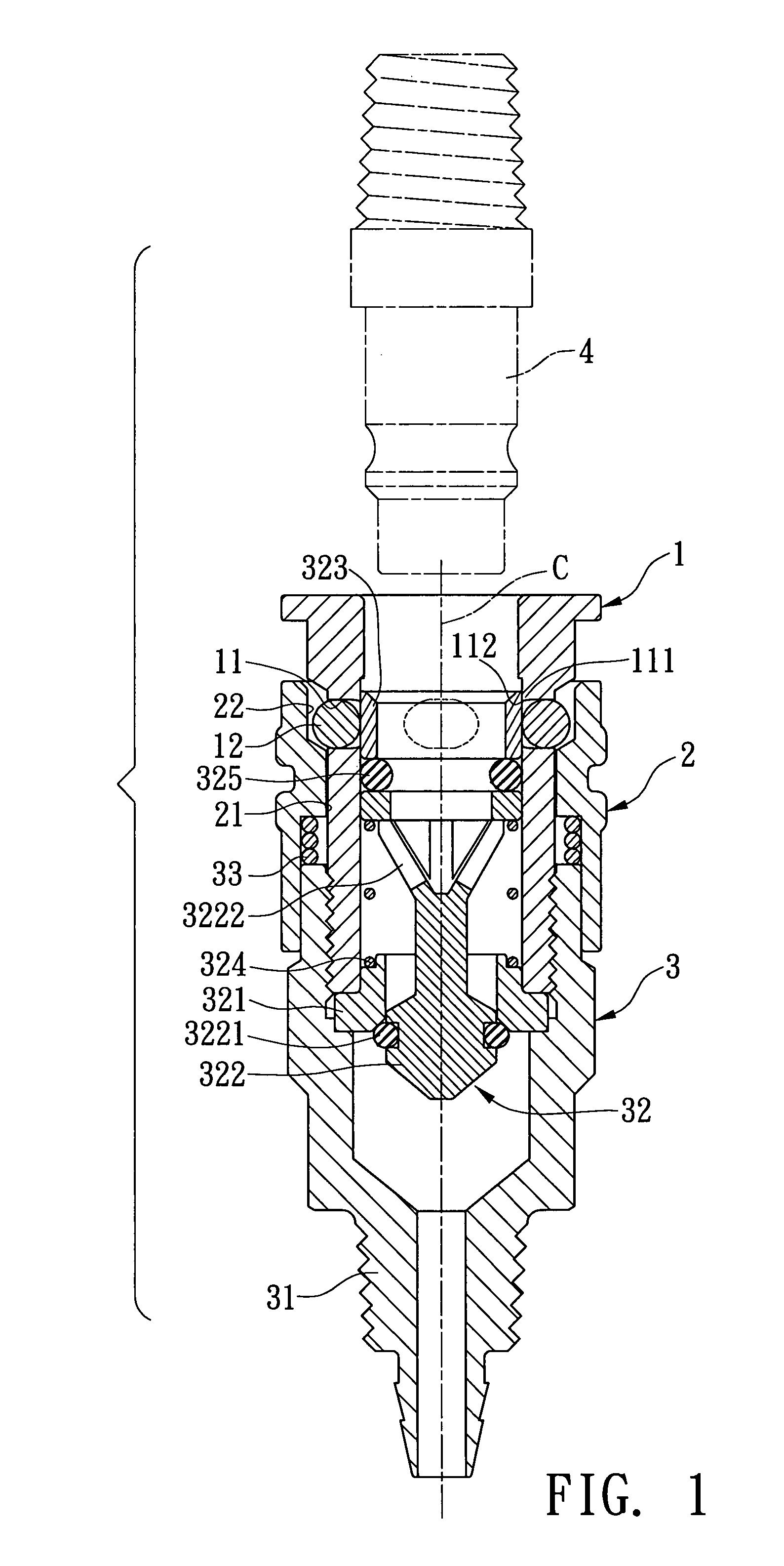
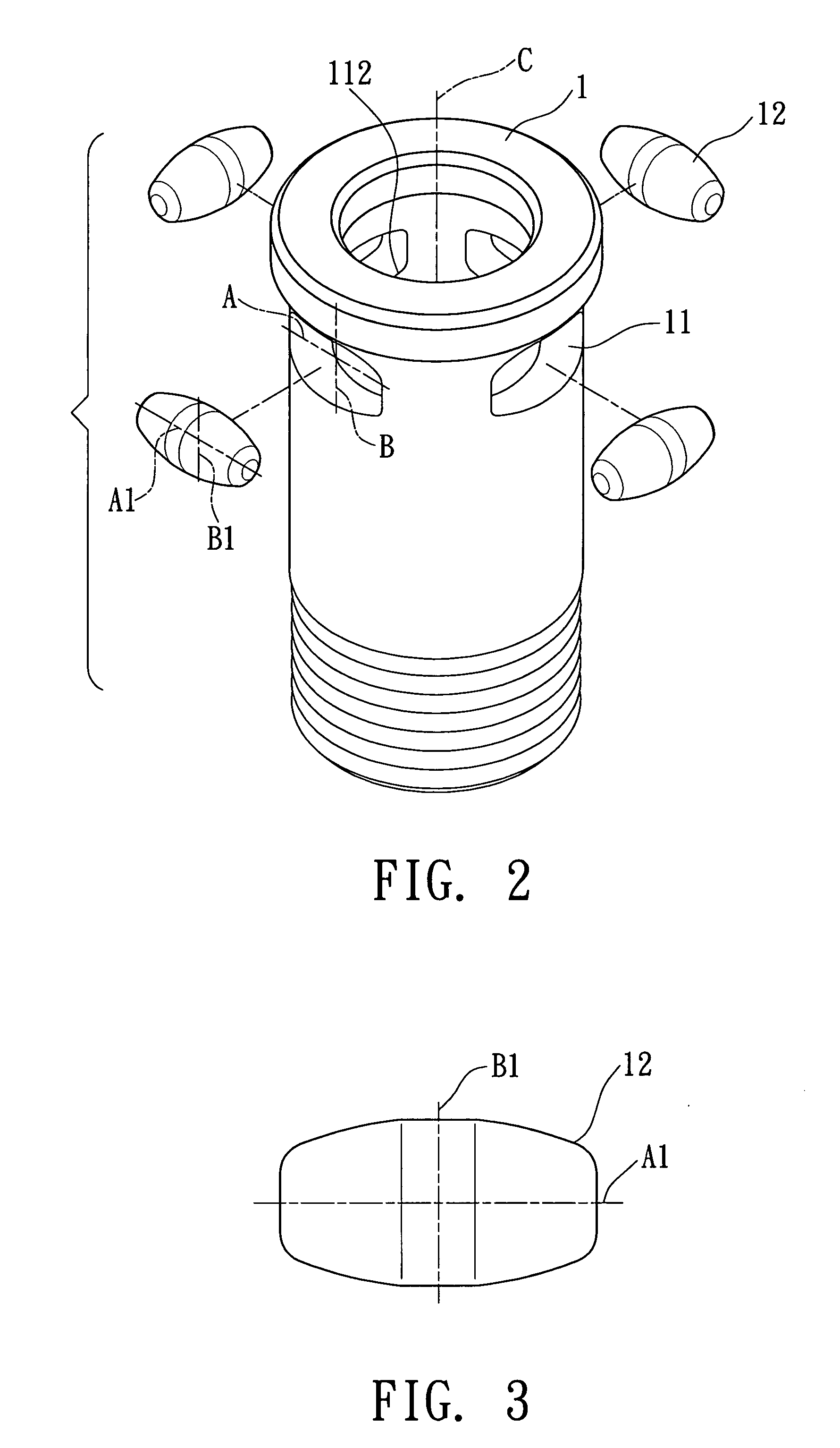
[0013]Referring to FIGS. 1 to 3, the connection device of the present invention comprises an inner tube 1 having a central path and a plurality of elongate holes 111 are defined through a wall thereof. Each of the elongate holes 111 includes a long axis “A” which is perpendicular to a longitudinal axis “C” of the inner tube 1, and a short axis “B” which is parallel to the longitudinal axis “C” of the inner tube 1. A plurality of openings 112 are defined in an inner surface of the inner tube 1 and communicate with the elongate holes 11 respectively.

[0014]Further referring to FIG. 5, a plurality of oval-shaped beads 12 are movably engaged with the elongate holes 111. Each of the beads 12 includes a long axis “A1” and a short axis “B1”. A length “L4” of each bead 12 is sized such that two rounded ends of each of the beads 12 along the long axis “A1” are received in the elongate hole 111 corresponding thereto. A part of each of the beads 12 in the direction of the short axis “B1” protru...


PUM


Abstract

A connecting device includes an inner tube having a plurality of elongate holes and a plurality of oval-shaped beads are movably engaged with the elongate holes. A plurality of openings are defined in an inner surface of the inner tube and communicate with the elongate holes respectively. A valve unit is movably located in the inner tube and includes a collar which removably closes the openings. An outer tube is movably mounted to an outer surface of the inner tube. An inlet member is connected to a first end of the inner tube. A part in short axis of each of the beads protrudes beyond the opening of the inner tube so as to provide a larger contact area with the head of hose when the head of hose is inserted into the inner tube to push the collar away from the openings.

Description

FIELD OF THE INVENTION[0001]The present invention relates to a connection device for quickly and securely connecting a connection head of hoses of pneumatic tools.BACKGROUND OF THE INVENTION[0002]A conventional connection device 9 for quickly connecting hose head 96 is shown in FIGS. 6 and 7, and generally includes an inner tube 91 which includes a top opening and an inlet member 93 is threadedly connected to the bottom of the inner tube 91. The inlet member 93 includes a valve unit 931 located in the inner tube 91. A first spring is connected between the valve unit 931 and the inlet member 93. An outer tube 92 is movably mounted to the inner tube 91 with a second spring 95 connected between the inner tube 91 and the outer tube 92 which is pushed and positioned at a first position by the second spring 95. A plurality of holes 911 are defined through a wall of the inner tube 91 and a bead 94 is movably engaged with each of the hole 911. The beads 94 are pushed inward by moving the ou...

Claims


Application Information

Patent Timeline
Patent Type & Authority Applications(United States)
IPC IPC(8): F16K15/18
CPCF16K15/021F16K15/026F16L37/42F16L37/22F16L37/40F16K15/181F16K15/1821
Inventor CHANG, JEN-CHIH
Owner CHANG JEN CHIH
Why Eureka
Try Eureka