Upright vacuum cleaner having suction path diverting valve

a vacuum cleaner and suction path technology, applied in the field of upright vacuum cleaners, can solve the problems of inability to easily reach the type vacuum cleaner, canister type vacuum cleaner can easily clean hard-to-clean areas,

Inactive Publication Date: 2009-04-09
SAMSUNG GWANGJU ELECTRONICS CO LTD
View PDF5 Cites 11 Cited by
  • Summary
  • Abstract
  • Description
  • Claims
  • Application Information

AI Technical Summary

Benefits of technology

[0017]Accordingly, as the operating member is released from the pressure by the extension pipe and upwardly and elastically supported by the return spring, the valve member turns in a normal direction through the link, thereby allowing the first and the second suction ducts to fluidly communicate with each other, and as the operating member is pressed by the extension pipe and thus turns the link in a reverse direction, the valve member allows the suction inlet body to fluidly communicate with the first suction duct.

Problems solved by technology

Accordingly, the canister type vacuum cleaner can easily clean hard-to-clean areas such as floors, stairs, and narrow areas that the upright type vacuum cleaner cannot easily reach.

Method used


Image

  • Upright vacuum cleaner having suction path diverting valve
  • Upright vacuum cleaner having suction path diverting valve
  • Upright vacuum cleaner having suction path diverting valve

Examples


Embodiment Construction

[0032]Certain exemplary embodiments of the present disclosure will be described in greater detail with reference to the accompanying drawings.

[0033]In the following description, the same drawing reference numerals are used for the same elements even in different drawings. The matter defined in the description, such as detailed construction and elements, are provided to assist in a comprehensive understanding of the disclosure. Thus, it is apparent that the exemplary embodiments of the present disclosure can be carried out without this specifically defined matter. Also, well-known functions or constructions are not described in detail since they would obscure the disclosure with unnecessary detail.

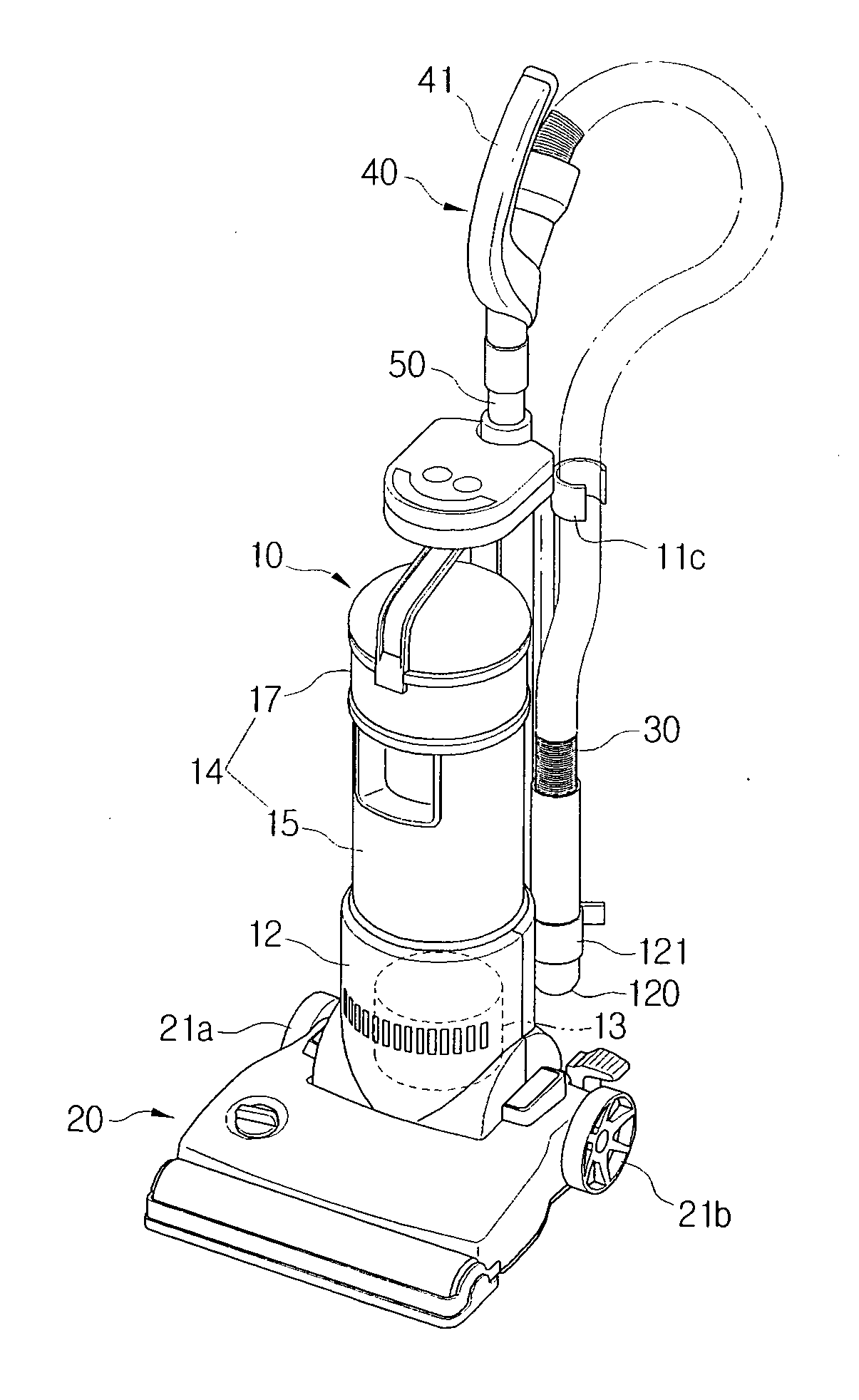
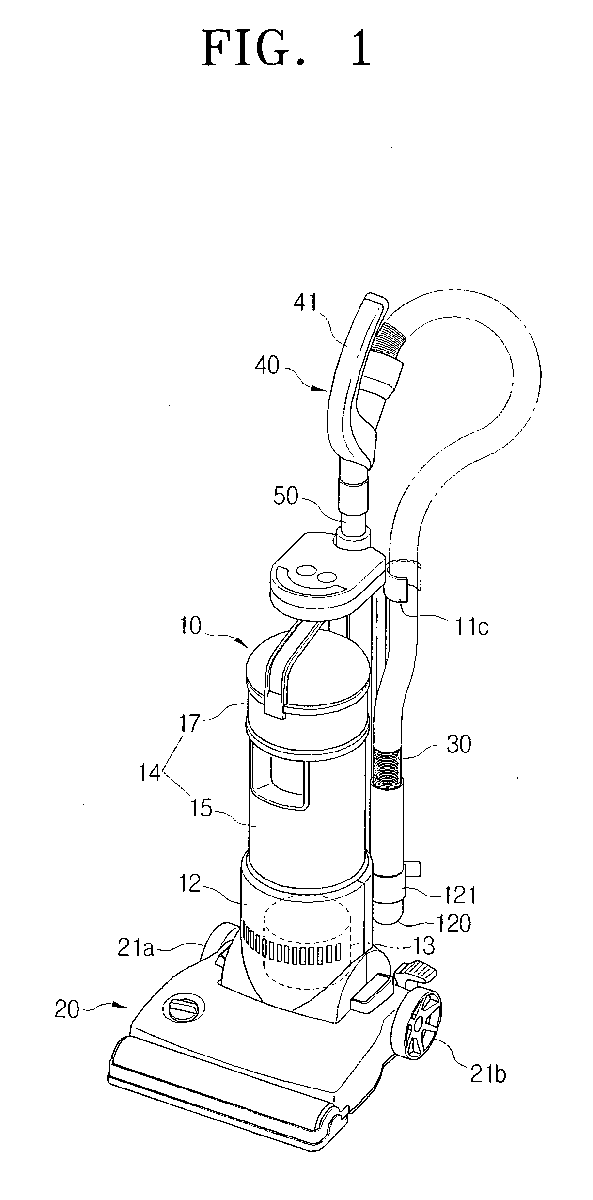
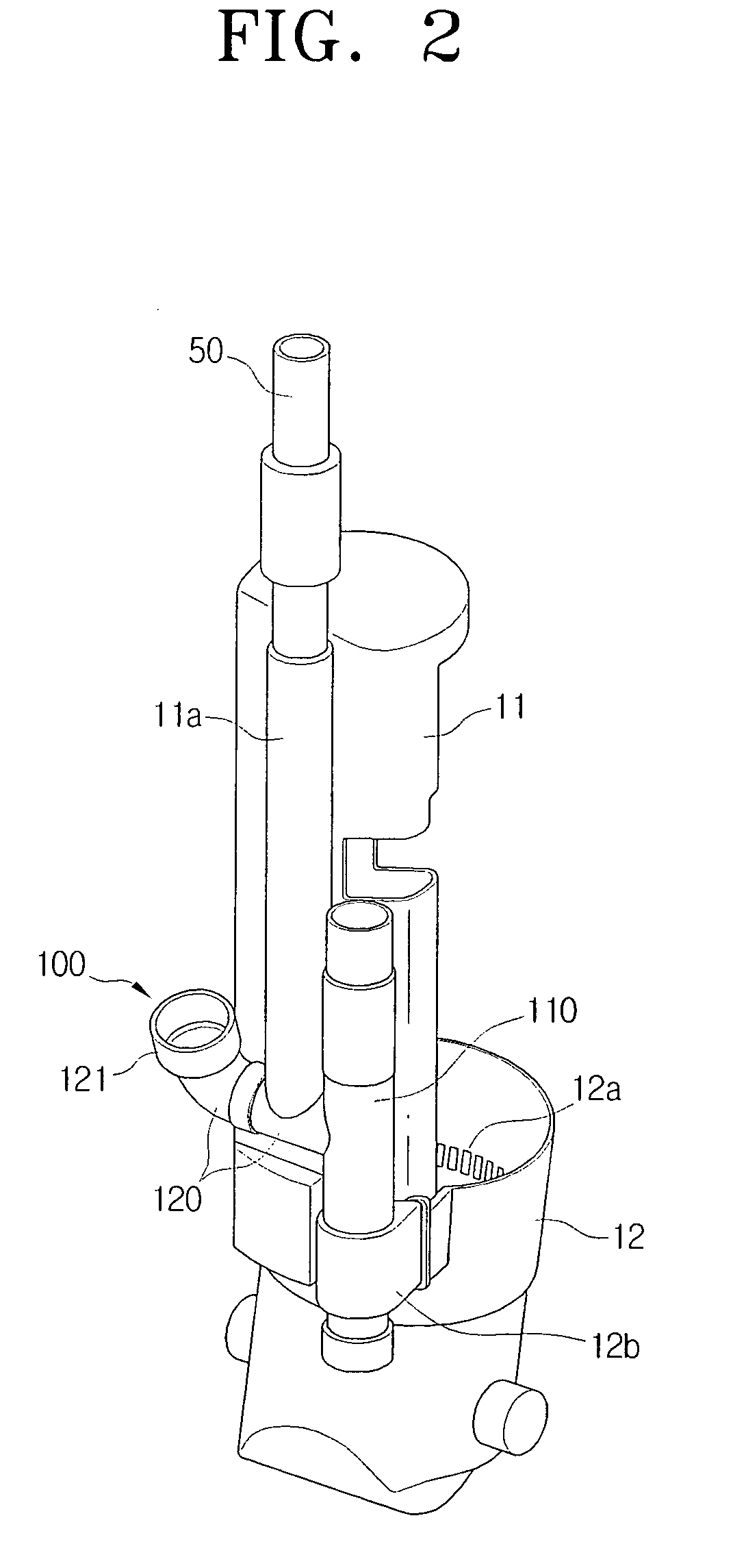
[0034]Hereinafter, a suction path diverting valve of an upright vacuum cleaner according to a first exemplary embodiment of the present disclosure will now be described in detail with reference to the drawings.

[0035]Referring to FIGS. 1 and 2, an upright vacuum cleaner according to a first ...


PUM


Abstract

An upright vacuum cleaner is provided that includes a cleaner body having a suction motor, a dust-collecting unit, and a body frame where the suction motor and the dust-collecting unit are disposed, a suction inlet body which is hinged to a lower end of the body frame, a hose which has one side fluidly communicating with the body frame and the other side fluidly communicating with an extension pipe through a manipulation handle, and a suction path diverting valve which is disposed on the body frame and has a valve member elastically arranged on a suction path. As the extension pipe is inserted into or withdrawn from a socket on the body frame, the valve member selectively diverts the suction path to a first suction path flowing from the suction inlet body to the dust-collecting unit or a second suction path flowing from the extension pipe to the dust-collecting unit.

Description

CROSS-REFERENCE TO RELATED APPLICATIONS[0001]This application claims the benefit under 35 U.S.C. §119(a) of Korean Patent Application No. 10-2007-0101070, filed on Oct. 8, 2007, in the Korean Intellectual Property Office, the entire disclosure of which is hereby incorporated by reference.BACKGROUND OF THE INVENTION[0002]1. Field of the Invention[0003]Methods and apparatuses consistent with the present disclosure relate to a cleaner, and more particularly, to an upright vacuum cleaner which is capable of selecting a suction path from a suction inlet body or from an extension pipe connected to a cleaner body to draw in dust from a cleaning surface using a suction force generated by a driven motor of the cleaner body.[0004]2. Description of the Related Art[0005]In general, vacuum cleaners can be largely divided into two main types, namely an upright type vacuum cleaner and a canister type vacuum cleaner. The upright type vacuum cleaner has a suction inlet body directly connected to a c...

Claims


Application Information

Patent Timeline
Patent Type & Authority Applications(United States)
IPC IPC(8): A47L5/00A47L9/10A47L9/00
CPCA47L5/32A47L9/248A47L9/0072A47L5/28A47L5/24
Inventor LEE, BYUNG-JOPARK, JOUNG-SOOKIM, TAE-GWANGHAN, JUNG-GYUNKIM, SEE-HYUN
Owner SAMSUNG GWANGJU ELECTRONICS CO LTD
Why Eureka
Try Eureka