Linear pneumatic gripper

Active Publication Date: 2009-05-21
GIMATIC SRL
View PDF7 Cites 20 Cited by
  • Summary
  • Abstract
  • Description
  • Claims
  • Application Information

AI Technical Summary

Benefits of technology

[0005]Starting from this introduction, one object of the present invention is to avoid the above mentioned drawbacks and disadvantages, and therefore to provide a liner pneumatic gripper made up of a limited number of components and where some components have a dual function.
[0008]In this way the oscillation pins of the jaws have at the same time the additional function of connecting and blocking the components to form the gripper body and which can also be achieved using different materials, thus enabling a simpler and less expensive manufacture of the device.

Problems solved by technology

However, the linear grippers known up to now are made up of several elements which are assembled also with the use of bolts and that for their combination they can be the cause of defects in the function of the gripper; in fact, possible dimension errors in the single components and / or the coupling tolerances may also considerably influence the precision and parallelism of the movement of the jaws.

Method used


Image

  • Linear pneumatic gripper
  • Linear pneumatic gripper
  • Linear pneumatic gripper

Examples


Embodiment Construction

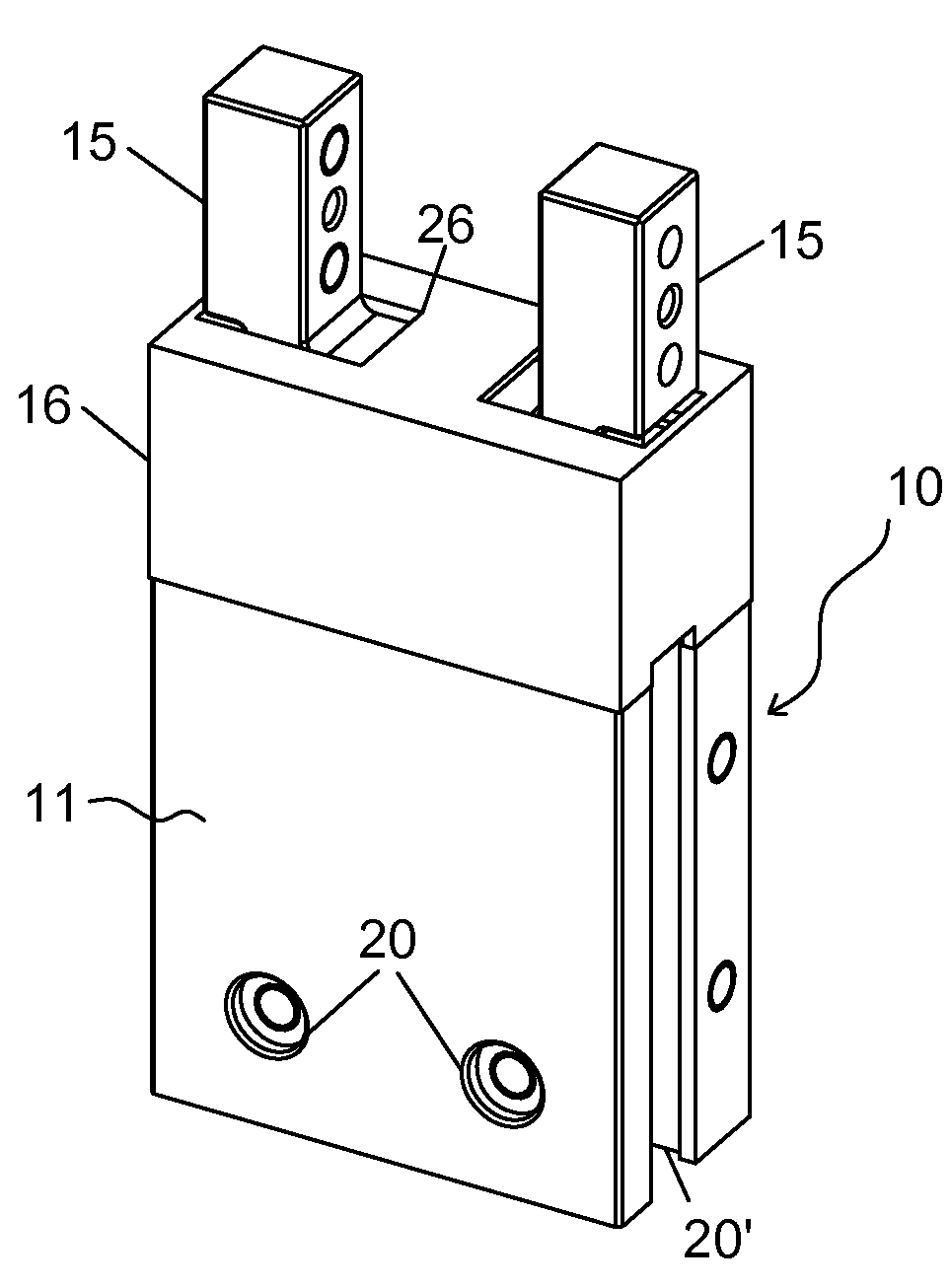
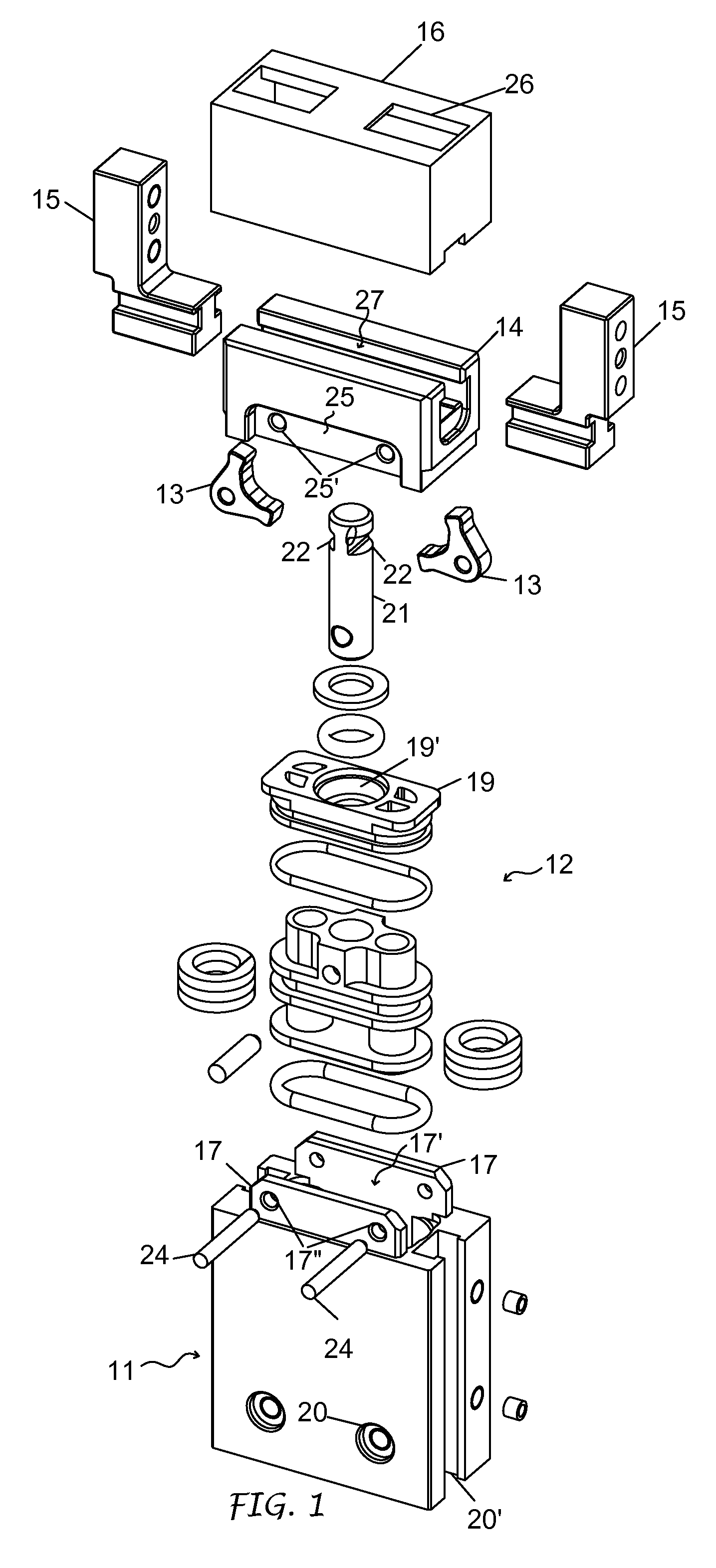
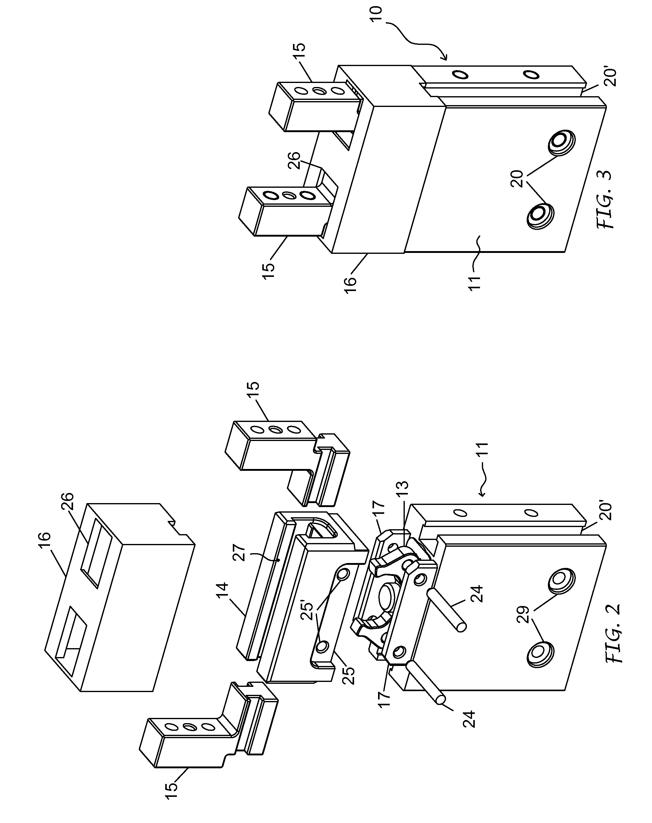
[0016]As shown, the linear pneumatic gripper 10 basically comprises a gripper body 11, a control piston 12, two oscillation drive levers 13, a guide test 14, a pair of jaws 15 and a protective cover 16.

[0017]The body of the gripper 11 is made up of a base element that has, at one of its ends, two parallel tongues 17 delimiting between them an opening 17′ and which are provided with two transversal bores 17″.

[0018]Internally, the body forms a chamber 18 closed at one end, whereas at the opposite end, the one facing towards the tongues 17, is closed by a plug 19 with an intermediate bore 19′. Furthermore, the body 11 has bores 20 on two lateral sides and a groove 20′ on each of the other two walls.

[0019]The control piston 12 is housed and slides in the chamber 18 and is equipped with a stem 21, which fits tight into the intermediate bore 19′ of the plug 19 and which has at its end, on opposite sides, two puller slots 22. The piston 12 can be cylindrical or not cylindrical, single acti...


PUM


Abstract

The invention concerns a linear pneumatic gripper that has a gripper body comprising a base element (11), in which a chamber (18) has been provided for a piston (12) and which supports two drive levers (13) oscillating on relative fulcrums or pins (24) and connected to said piston, and a guide head (14) associated with said base element and having a guide groove for two jaws connected to the drive levers. The guide head is fixed to the base element of the gripper body by means of the oscillation fulcrums or pins (24) of said drive levers.

Description

FIELD OF THE INVENTION[0001]This invention concerns in general the pneumatic gripper sector used for gripping items being machined and / or for automatic handling, and refers in particular to a type of pneumatic gripper that has a pair of jaws which move linearly in opposite directions to open and close by means of a pneumatic control piston with single or double action.STATE OF THE TECHNIQUE[0002]The linear pneumatic grippers for the above use are well known, both as regards to how they are structured and how they function. They can differ in form, dimensions and capacity.[0003]The type of pneumatic grippers taken into consideration in this case, basically comprise a body forming a chamber, a piston positioned and moving alternately in said chamber under the action of a fluid under pressure, and a pair of gripper jaws associated with said body and movable in opposite directions. The piston is connected to the jaws by means of operating levers, assembled by means of fulcrums or oscill...

Claims


Application Information

Patent Timeline
IPC IPC(8): B25J15/08B25B1/02B25B1/18B25B5/06
CPCB25J15/028
Inventor MAFFEIS, GIUSEPPE
Owner GIMATIC SRL
Why Eureka
Try Eureka