Solar thermal energy collector

a solar thermal energy and collector technology, applied in the field of solar thermal energy, can solve the problems of limited heat transfer ability of conventional designs and collectors

Inactive Publication Date: 2009-06-04
RGT UNIV OF CALIFORNIA +1
View PDF47 Cites 23 Cited by
  • Summary
  • Abstract
  • Description
  • Claims
  • Application Information

AI Technical Summary

Problems solved by technology

Conventional designs are limited in their ability to transfer heat from the collector.

Method used


Image

  • Solar thermal energy collector
  • Solar thermal energy collector
  • Solar thermal energy collector

Examples


Embodiment Construction

[0015]Embodiments of the present invention provide devices, methods and systems for collection and / or transferring of solar thermal energy. In this regard, embodiments of the present invention may provide inexpensive and efficient manners for collection of solar thermal energy.

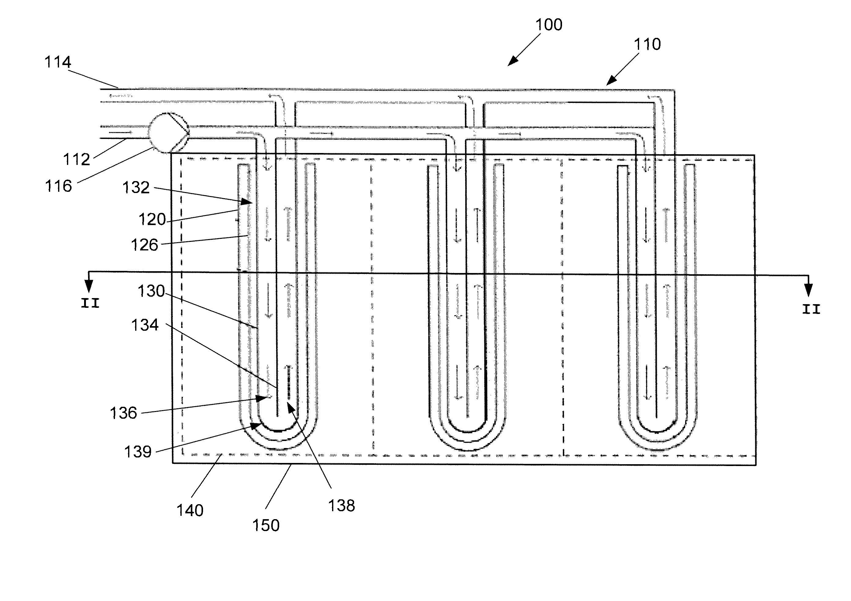
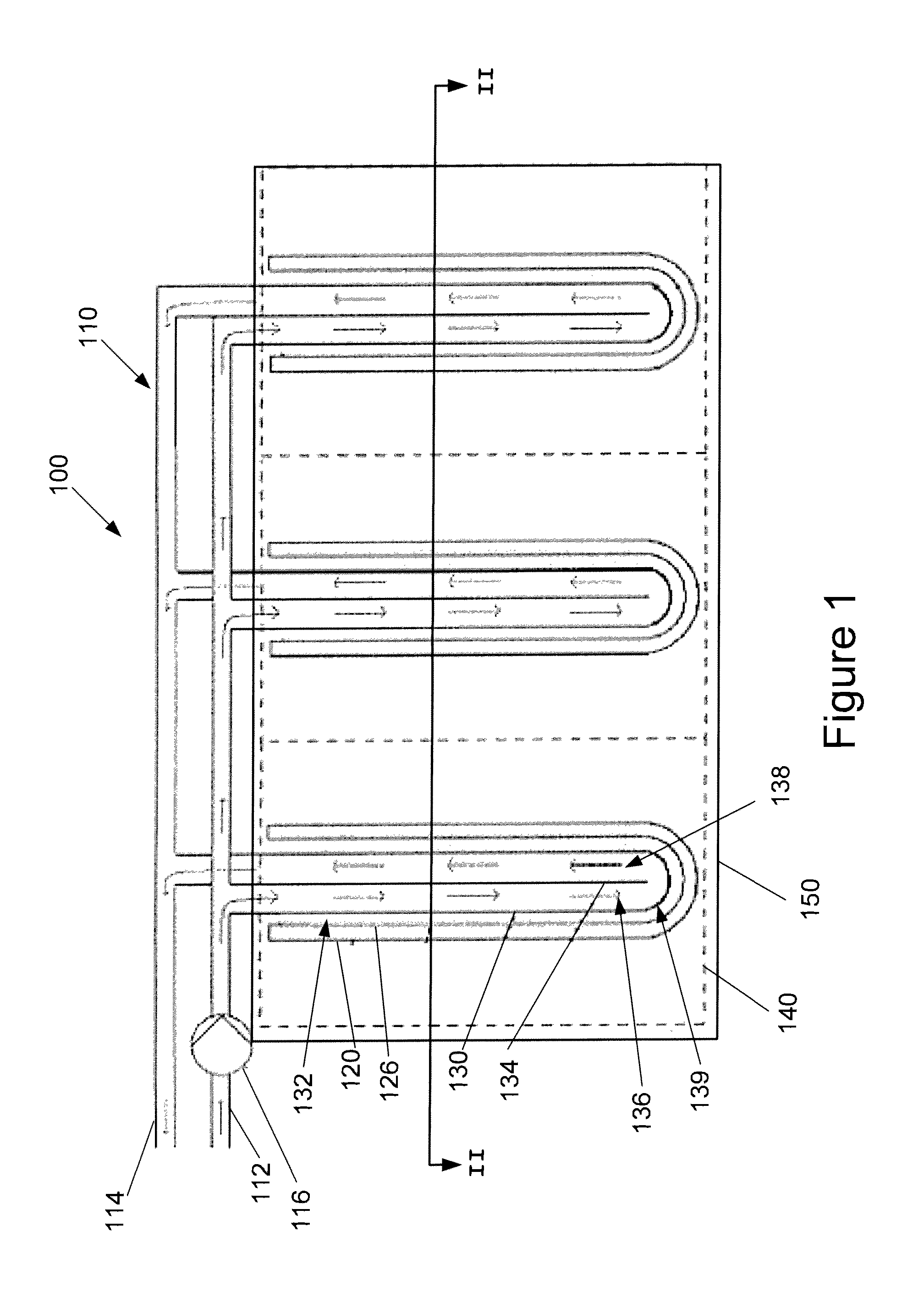
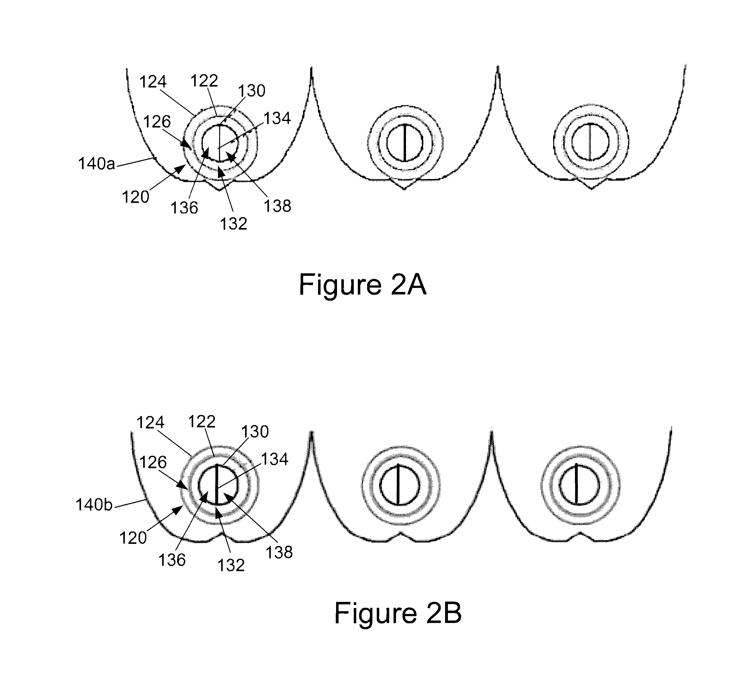
[0016]Referring to FIGS. 1, 2A and 2B, a solar thermal energy collector according to an embodiment of the present invention is illustrated. In the illustrated embodiment, a collector 100 includes one or more receptacles 120 coupled to a manifold 110. The manifold 110 includes an inlet pipe 112 and an outlet pipe 114 for circulating fluid through the manifold 110 and the collector 100. A pump 116 is provided to circulate the fluid 110. The dimensions of the inlet pipe 112, the outlet pipe 114 and the pump 116 may be selected according to the requirements of the specific implementation of the collector 100.

[0017]The manifold 110 is coupled to one or more receptacles 120. The number of receptacles 120 may be sele...


PUM


Abstract

A solar thermal energy collector includes a receptacle and a tube positioned within the receptacle and having a closed end. The tube includes a divider cross-sectionally bifurcating the tube. The divider is spaced apart from the closed end of the tube to allow fluid communication between two bifurcated portions of the tube. A fluid is circulated through the two bifurcated portions of the tube for transferring of the solar thermal energy.

Description

BACKGROUND OF THE INVENTION[0001]The present invention relates generally to the field of solar thermal energy. In particular, the present invention relates to solar thermal energy collectors.[0002]Solar thermal collectors have been utilized for over 20 years. The designs have varied from flat plate, box, air, integral, unglazed more commonly to parabolic troughs and dishes and full power towers. Though they have been commercially available for over 20 years, recent designs of evacuated tubes have become more efficient and less costly, allowing them to be both commercially and domestically available as well as more widely utilized. Some devices contain heat removal inserts that are placed within the tubes that serve the purpose of transferring the collected energy to a heat-transfer fluid and are used to transfer heat to a manifold located at the end of the tubes or in connection with the inserts.[0003]Conventional designs are limited in their ability to transfer heat from the collec...

Claims


Application Information

Patent Timeline
Patent Type & Authority Applications(United States)
IPC IPC(8): F24J2/24F24J2/30F24S10/30F24S10/40F24S10/70F24S23/70
CPCF24J2/0483Y02E10/44F24J2/1047F24J2/055F24S23/80F24S10/45F24S10/25
Inventor GEE, RANDY C.WINSTON, ROLAND
Owner RGT UNIV OF CALIFORNIA
Why Eureka
Try Eureka