Multiple geofence system for vehicles

a geofencing and vehicle technology, applied in vehicle components, anti-theft devices, instruments, etc., can solve the problem of limiting the territorial extent of a permitted operational area of a mobile platform

Inactive Publication Date: 2009-06-04
INT TRUCK INTPROP LLC
View PDF15 Cites 112 Cited by
  • Summary
  • Abstract
  • Description
  • Claims
  • Application Information

AI Technical Summary

Benefits of technology

[0007]Additional effects, features and advantages wil

Problems solved by technology

The second geofence limits the territorial extent of a permitted operational area

Method used


Image

  • Multiple geofence system for vehicles
  • Multiple geofence system for vehicles
  • Multiple geofence system for vehicles

Examples


Embodiment Construction

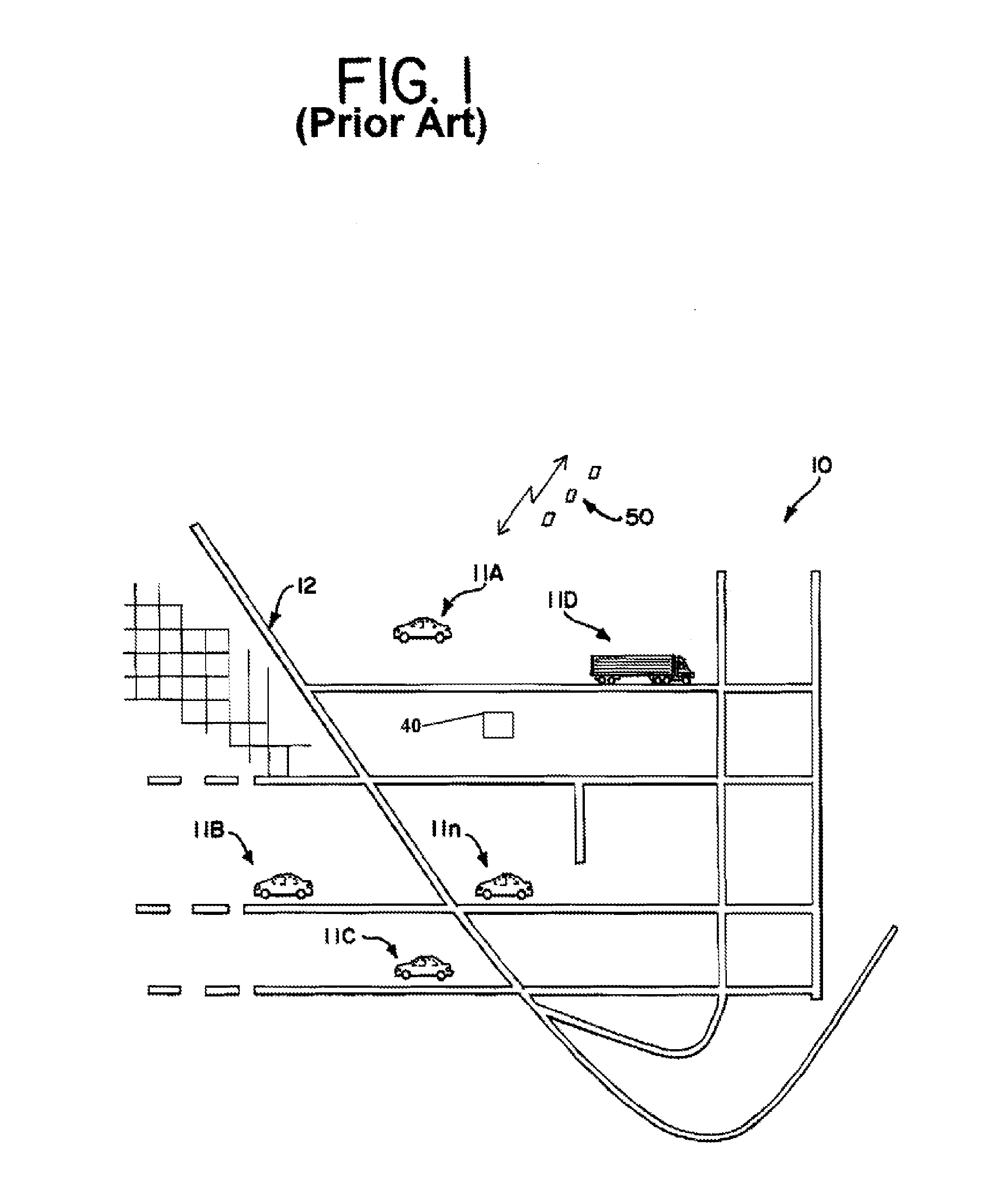
[0013]Referring now to FIG. 1, vehicles 11(A), 11(B), 11(C) . . . 11(n) travel on the road network 12 in the region 10. The vehicles 11 may include cars or trucks. Some or all of the vehicles 11 include suitable equipment that enables them to receive the global positioning information broadcast by a global positioning satellite constellation 50 and thus are mobile platforms with respect to which a geofence may be raised. Geofences (not shown) may be erected on region 10 through interaction of data processing equipment on board the vehicles with positioning data, or by response of a central control facility 40 to which the positioning data is reported. Each vehicle may be programmed with individual sets of responses so that the geofences applied to each vehicle are unique to that vehicle both as to location and as to the character of the responses.

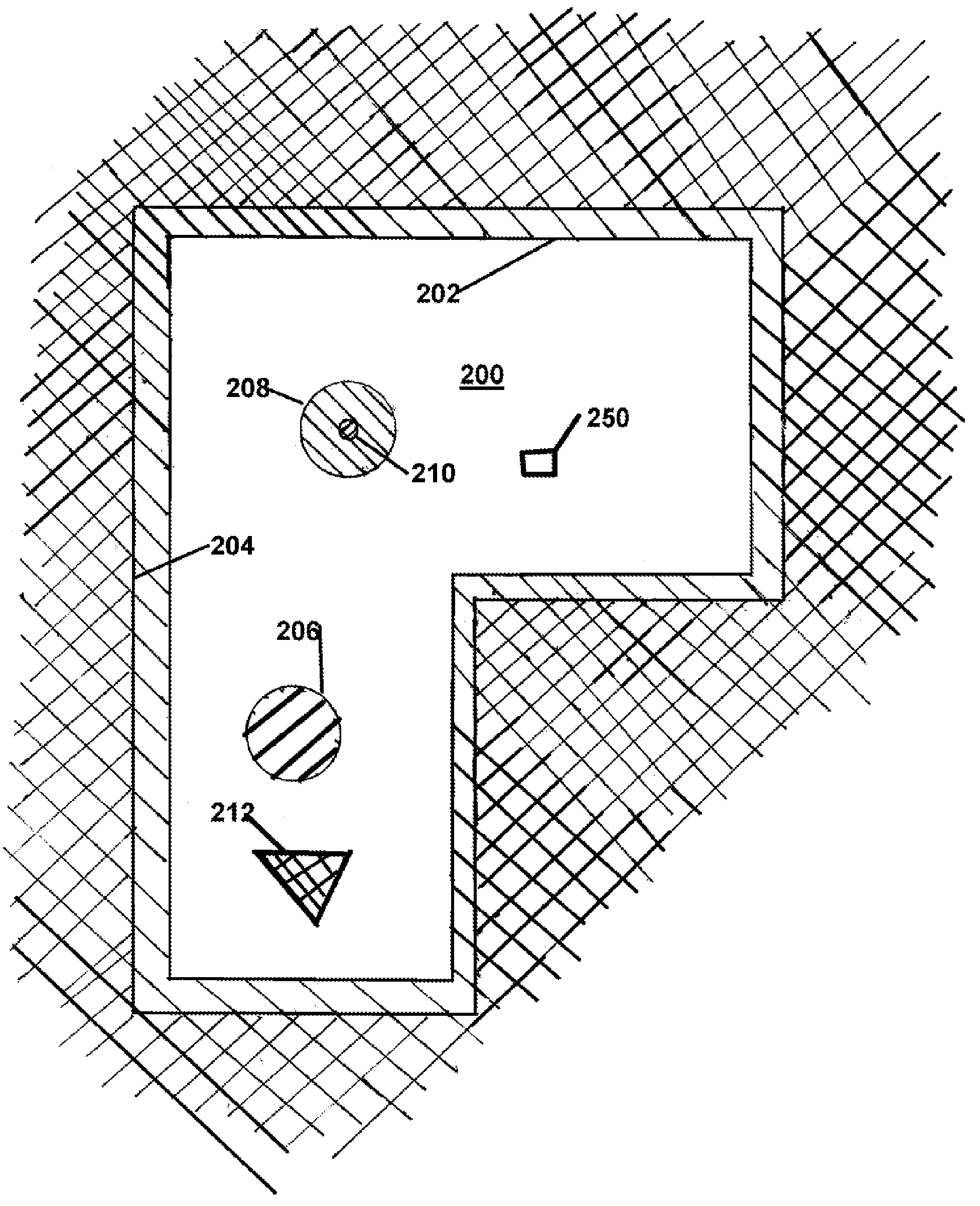
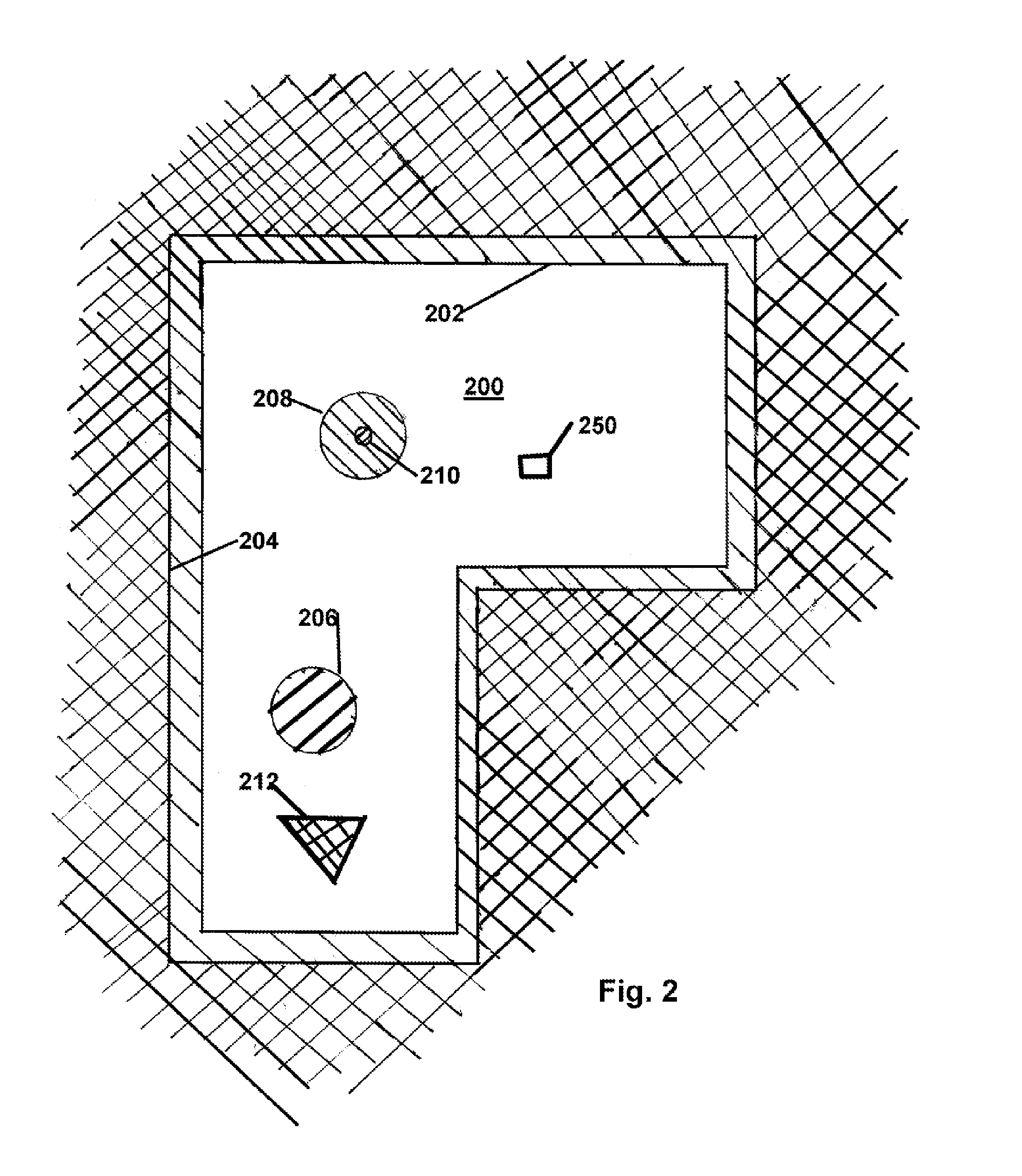
[0014]Referring to FIG. 2, a geofence may be based on an irregular polygon, a circle, a regular rectangle, or a combination of these shape...


PUM


Abstract

At least first and second geofences are established. The first geofence provides for indicating to an operator of a vehicle a limit to the territorial extent of a permitted operational area for the vehicle. The second geofence limits the territorial extent of a permitted operational area for the mobile platform, typically by limiting the mobility of the mobile platform. The first and second geofences are located with respect to one another and the permitted operational area so that with movement through the limits of the permitted operational area, the mobile platform encounters the first geofence no later than it encounters the second geofence.

Description

BACKGROUND OF THE INVENTION[0001]1. Technical Field[0002]The invention relates to geofencing for vehicles, and more particularly, to providing multiple geofences to allow nested, virtual regions and staggered responses to geofence violations.[0003]2. Description of the Problem[0004]A geofence may be defined in part as a virtual spatial boundary. Geofences are a byproduct of the marriage of mobile, inexpensive telecommunications platforms and data processing systems. While not dependent upon global positioning systems in theory, their accuracy is greatly enhanced by making use of global positioning systems to provide accurate and precise determination of the location of the mobile platform. A geofence is manifested in programmed responses of a data processing system installed on the mobile platform responsive to changes in the platform's position. Typically the positions which produce a given set of responses define a contiguous region. The edges of the region become a virtual bounda...

Claims


Application Information

Patent Timeline
IPC IPC(8): G08G1/123B60R25/00B60R25/04B60R25/10
CPCB60R25/00G08G1/207B60R25/1012B60R25/04
Inventor BENDER, BURNELL L.
Owner INT TRUCK INTPROP LLC
Why Eureka
Try Eureka