Monitoring System for Monitoring Coverage of Broadcast Transmissions

a broadcast transmission and monitoring system technology, applied in the field of broadcast transmissions, can solve the problems of not being able to have not having a known approach and system optimal for monitoring tv signals, and unable to achieve a relatively complete knowledge, so as to achieve efficient monitoring and high spatial capillary

Active Publication Date: 2009-07-16
TELECOM ITALIA SPA
View PDF1 Cites 57 Cited by
  • Summary
  • Abstract
  • Description
  • Claims
  • Application Information

AI Technical Summary

Benefits of technology

[0020]In view of the foregoing, the Applicant has tackled the problem of providing a relatively simple, low-cost monitoring system for broadcast signals adapted to overcome the drawback of the known systems, particularly capable of performing, without excessive burden for the broadcaster, a time-continuous monitoring of the broadcasted signal even where it is at least potentially received, i.e. in points of the broadcasting area where a user might install an antenna for receiving and enjoying the TV broadcast transmissions, with high spatial capillarity, and not necessarily attended by human operators.
[0022]The technique of the present invention offers at least the following advantages:

Problems solved by technology

The Applicant has observed that the known approaches and systems for monitoring TV signals are not optimal, and presents several drawbacks.
Such an approach totally lacks of spatial capillarity, and does not allow to have a relatively complete knowledge of the actual TV signal coverage within the area of interest Moreover, the measurements are typically taken only once per each location, so the data are not time continuous, which prevents a timely estimation of possible TV signal degradations due to transmission stations' malfunctioning or to possible interferences caused by other TV signals, possibly from unlicensed broadcasters.
A further disadvantage of that technique is that the results of the measurements cannot be immediately exploited: the measurements are in fact collected on the portable system and possible corrective actions for improved signal coverage can be taken only at the end of of the test campaign.
The monitoring system proposed by Tektronix is sophisticated, but for this reason it is also costly.

Method used


Image

  • Monitoring System for Monitoring Coverage of Broadcast Transmissions
  • Monitoring System for Monitoring Coverage of Broadcast Transmissions
  • Monitoring System for Monitoring Coverage of Broadcast Transmissions

Examples


Embodiment Construction

)

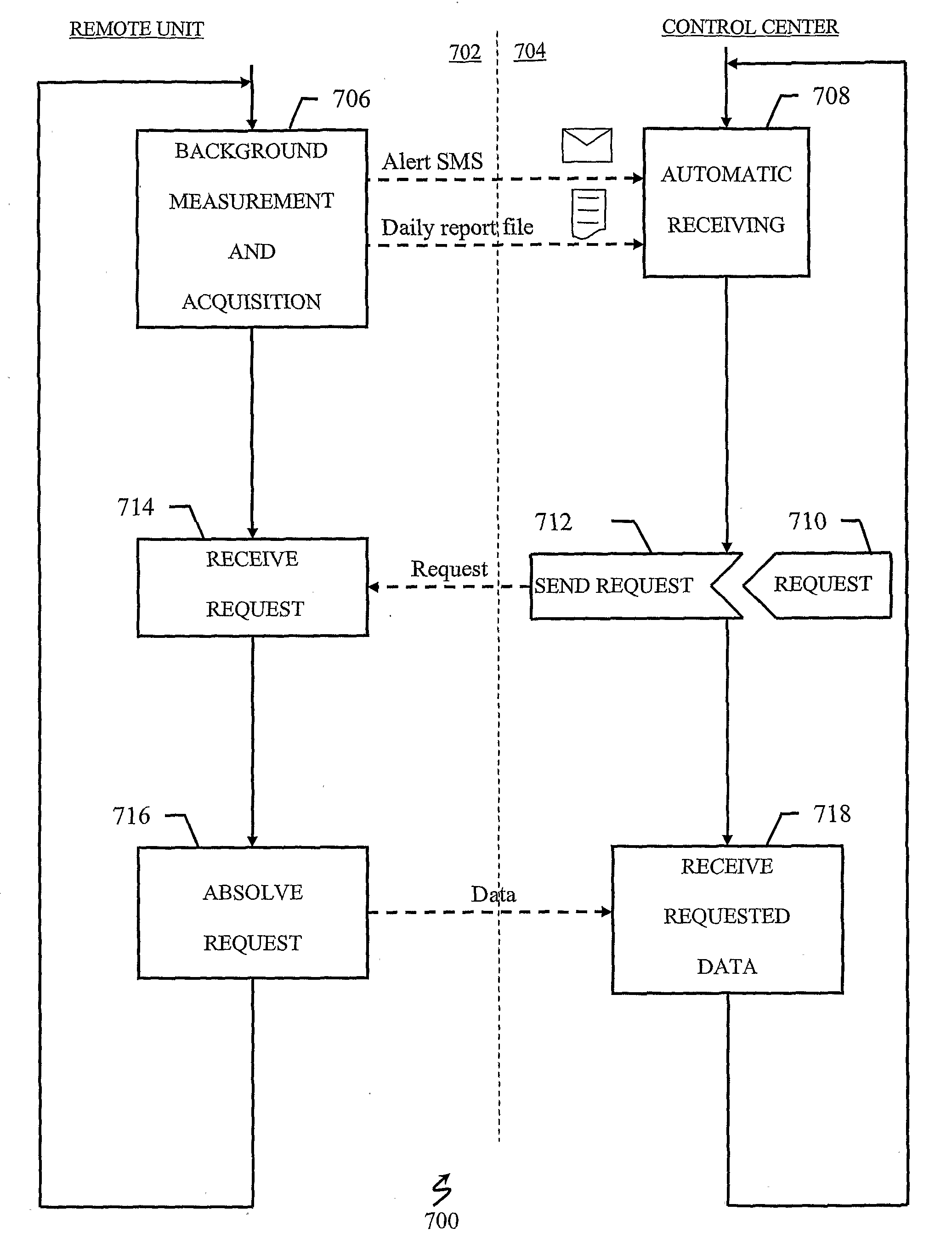
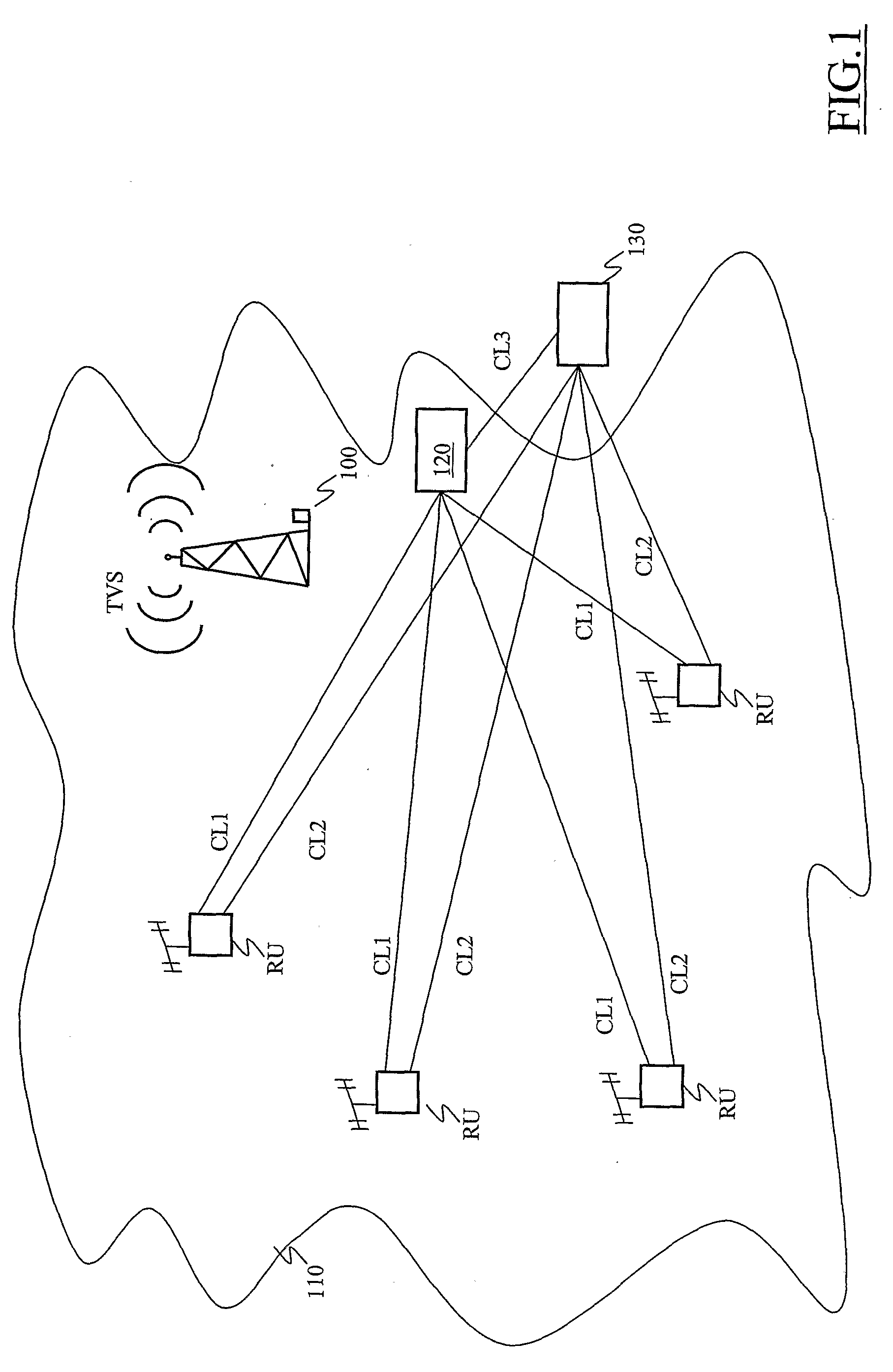
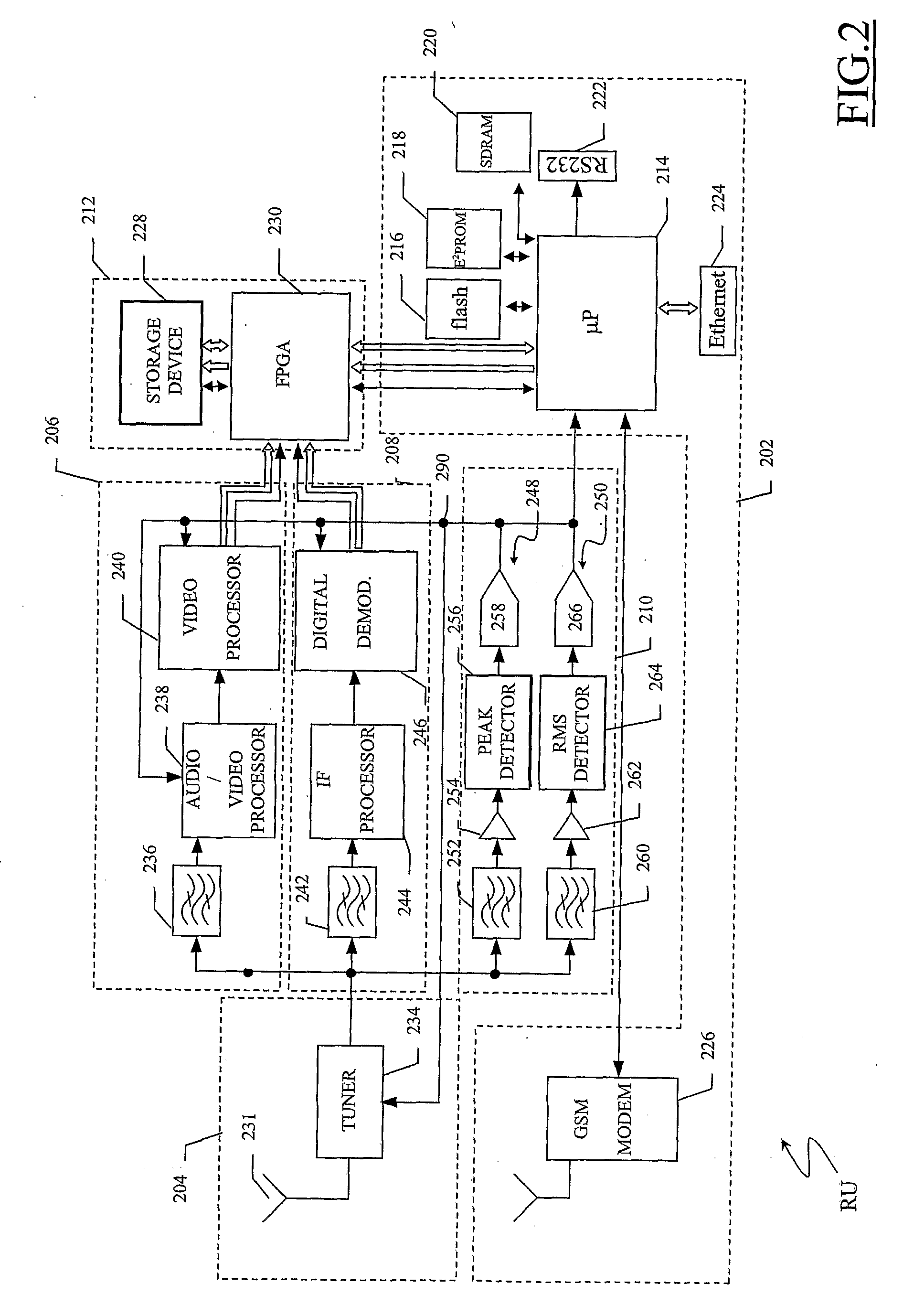
[0065]Making reference to the drawings, in FIG. 1 a portion of a broadcast transmission system, particularly but not imitatively a broadcast system of a TV network, is pictorially shown, wherein a monitoring system according to an embodiment of the present invention is advantageously exploited.

[0066]A TV signal transmitting antenna 100 represents a generic transmission station of the TV network, and broadcasts a TV signal TVS within a corresponding area of broadcasting 110, being a geographic area of interest covered, i.e., reached, by the TV signal TVS irradiated by the transmitting antenna 100.

[0067]The TV signal TVS may be either an analog TV broadcasting signal, or a Digital TV (DTV) broadcasting signal. For example, the TV signal TVS may comply with any one of the known TV broadcasting standards, like for example the PAL, SECAM, NTSC DVB-T. In the case the TV signal TVS is analog, it comprises an Amplitude-Modulated (AM) signal for the video content (pictures), and a Frequency...


PUM


Abstract

A system for monitoring television signals broadcast by at least one transmission antenna in a broadcast area includes a monitoring control center and a plurality of remote monitoring units distributed in television signal receiving locations of the broadcast area remote from the transmission antenna. The remote monitoring units are configured to receive the television signals irradiated in the respective locations, process the television signals and send to the monitoring control center information related to the processed television signal. In particular, the remote monitoring units include a receiver adapted to receive the television signal, a measuring system adapted to perform measures on radio-electric features of the received television signal, and a communication system adapted to communicate measurement results to the remote monitoring center, exploiting a communication link between the remote monitoring unit and the control center.

Description

BACKGROUND OF THE INVENTION[0001]1. Technical Field of the Invention[0002]The present invention relates to the field of broadcast transmissions, such as terrestrial analog or digital TeleVision (TV). In particular, the invention relates to the monitoring of signals in broadcast transmissions.[0003]2. Description of Related Art[0004]In broadcast transmissions like terrestrial analog or digital TV, television sets are adapted to receive TV signals broadcast by transmission centers or stations; for example, a TV signal of a certain broadcaster can be broadcasted through a certain geographic area by means of one or more transmitting antennas, and can be received by television sets, connected to proper receiving antennas, located in the area of broadcasting. The geographic area wherein a certain TV signal can be received is also referred to as being “covered” by the signal.[0005]The features of a TV signal perceived at a particular location within the area of broadcasting depends on seve...

Claims


Application Information

Patent Timeline
Patent Type & Authority Applications(United States)
IPC IPC(8): H04N17/02H04W4/12
CPCH04B17/24H04B17/336H04B17/318
Inventor BESSONE, DANILOGIGLIOTTI, VINCENZOLUPANO, MICHELERINAUDO, ALFREDOSQUIZZATO, VALTER
Owner TELECOM ITALIA SPA
Why Eureka
Try Eureka