Unit for the transfer and distribution of a liquid and method of manufacturing the same

a technology of liquid and method, applied in the direction of packaging foodstuffs, tobacco, packaged goods, etc., can solve the problems of difficult exchange of wicks used in prior art dispensing devices, insufficient homogeneous distribution of volatile chemical substances in liquid in air flow, etc., to prevent softening of shafts and stabilize shafts

Inactive Publication Date: 2005-07-26
GIVAUDAN SA
View PDF5 Cites 11 Cited by
  • Summary
  • Abstract
  • Description
  • Claims
  • Application Information

AI Technical Summary

Benefits of technology

[0013]The refill according to the invention comprises a reservoir containing the liquid, an outlet opening and a shaft receiving passage starting at the outlet opening and projecting inward. The shaft receiving passage is suitable for receiving the shaft of the transfer unit as described above. Preferably the receiving passage is dimensioned to tightly embrace the shaft, as this stabilizes the transfer unit and a capillary effect can be achieved between the shaft and the walls of the receiving passage enhancing the capillary action of the shaft itself. Another embodiment of the shaft may be envisaged where lower-capillary action is required. This can be achieved through tapering of the shaft for the lower portion of ist length, such that it is not in intimate contact wiht the lower portion of the receiving passage. The refill and the shaft receiving passage may be moulded in one piece which can be produced at low cost. In a preferred embodiment the shaft receiving passage comprises a seal, e.g. a metal foil, plastic moulding, or any inpervious material that can be easily punctured isolating the liquid in the reservoir from the outside. Preferably, the seal is located at the bottom end of the passage and may be punctured by the shaft when fully introduced into the refill. A commercial embodiment of this could have the shaft partially introduced into the shaft receiving passage and the action of inserting the refill into the main unit causes the shaft to break the seal. To facilitate breaking the seal the shaft preferably comprises a cutting member at its bottom portion, e.g. a tip or a thorn or a knife-like element. Seal location at the bottom end of the passage is advantageous as the narrow passage protects the seal against accidental damage. The refill can thus be sold ready for use without an extra cover of the outlet opening, such as a lid, thus saving material, waste and manufacturing costs. Introduction of the shaft can be accomplished without spilling.
[0015]A coating of the lateral shaft faces respectively a layer around these faces impermeable to liquid is advantageous as it prevents softening of the shaft and stabilizes the shaft. Further, it enables the control of the dispensed amount as liquid flow can be stopped by tilting or turning the reservoir, thus preventing contact of the bottom portion with the liquid.

Problems solved by technology

However, the distribution of volatile chemical substances contained in the liquid in the air flow is not sufficiently homogenous when the air flow is brushing over the wick.
Further, in most cases dispensing a substance cannot be done without generation of an external air flow in order to evaporate a given amount of liquid per unit time.
The wicks used in prior art dispensing devices are difficult to exchange as they have to be mounted in such a way that the wick is arranged in a defined position relative to the reservoir.
This is rendered difficult as wicks are generally soft.
Further, the reservoir including the wick has to be tight to prevent spilling of the liquid and uncontrolled evaporation.
The same problem arises with a refill for such a device.

Method used


Image

  • Unit for the transfer and distribution of a liquid and method of manufacturing the same
  • Unit for the transfer and distribution of a liquid and method of manufacturing the same
  • Unit for the transfer and distribution of a liquid and method of manufacturing the same

Examples


Embodiment Construction

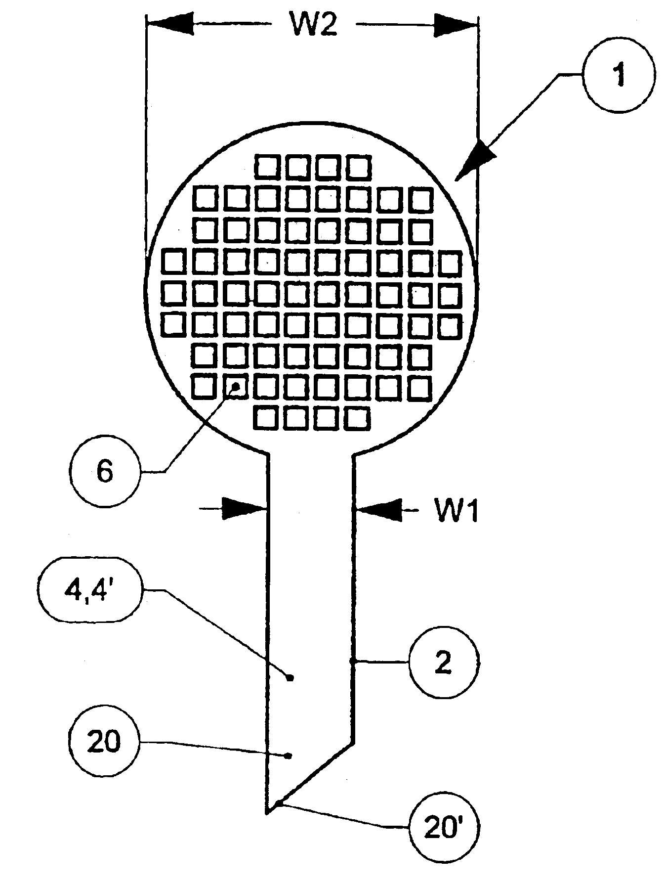
[0028]FIG. 1 shows a transfer unit 1 with an elongated shaft 2 and a screen 3. The shaft 2 consists of a first capillary medium 4, here absorbent card board 4′, preferably 1 to 4 mm thick. The shaft 2 may have, but is not restricted to a rectangular shape with a width W1 of preferably 5 to 10 mm. The length of the shaft 2 is greater than the width W1 and is chosen such that at least the bottom portion 20 of the shaft 2 is in contact with the liquid, e.g. a perfume, when introduced into a liquid reservoir. The bottom portion 20 has a tip 20′ to facilitate breaking a seal, as shown in FIG. 5a,b. The screen 3 consists of a second capillary medium 5 with a plurality of “small” openings 6 punched out to allow air to pass through, each opening 6 covering less than 5% of the total screen area. The width W2 of the circular screen 3 is about three times the width W1 of the shaft 2. Screen 3 and shaft 2 are made of the same material, a card sheet, i. e. in this embodiment for the second capil...


PUM

PropertyMeasurementUnit
thickaaaaaaaaaa
width W1aaaaaaaaaa
air permeableaaaaaaaaaa

Abstract

A unit (1) for the transfer and distribution of a liquid (27) using capillary action has an elongated shaft (2) and a screen (3). The shaft (2) includes a first capillary medium (4) suitable for drawing the liquid (27) from a reservoir (26) into the shaft (2) when a bottom portion (20) of the shaft (2) is disposed in the liquid. The screen (3) is connected to the shaft (2) and includes a second capillary medium (5) suitable for receiving the liquid (27) drawn by the first capillary medium (4) and distributing it over at least a major part of the screen (3) where it evaporates.

Description

[0001]This application is a division of application Ser. No. 09 / 856,744, filed May 25, 2001, now U.S. Pat. No. 6,708,897, which is a 371 of PCT / EP00 / 07489, filed Aug. 2, 2000.[0002]The present invention relates to a unit for the transfer and distribution of a liquid and a method of manufacturing the same according to claims 1 respectively 12. The invention further relates to a refill for a dispenser for volatile liquids according to claim 16.BACKGROUND OF THE INVENTION[0003]In order to transfer liquids it is known to use capillary action which is dependent on the cohesive forces within the liquid and the adhesive forces of the liquid to a capillary medium comprising small channels, e.g. pores or spaces between fibers. Such a capillary medium, e.g. a wick, being introduced through an opening into a reservoir, can therefore be used to draw a liquid out of said reservoir passively by means of capillary action only, i.e. without additional sucking. The transferred liquid may be used to ...

Claims


Application Information

Patent Timeline
Patent Type & Authority Patents(United States)
IPC IPC(8): A01M1/20A61L9/12B67D99/00A45D34/00A45D34/02B01J4/00B65D85/00
CPCA01M1/2033A01M1/2044A61L9/127B67D99/00
Inventor HART, GERALD LESLIENAISH, GUY EDWARDGOHIL, KISHEN
Owner GIVAUDAN SA
Why Eureka
Try Eureka