Heat pipe

A heat pipe and heat conductor technology, applied in the field of heat pipes, can solve the problems of small contact area between the tubular heat pipe and the heat source, not suitable for heat dissipation of small electronic products, damage to the internal structure of the heat pipe, etc.

Inactive Publication Date: 2010-01-06
HONG FU JIN PRECISION IND (SHENZHEN) CO LTD +1
View PDF0 Cites 13 Cited by
  • Summary
  • Abstract
  • Description
  • Claims
  • Application Information

AI Technical Summary

Problems solved by technology

The current heat pipe is usually a tubular structure. Since the contact area between the tubular heat pipe and the heat source is very small, the heat dissipation efficiency is not high, so it is not suitable for the heat dissipation of such small electronic products.
Some manufacturers directly flatten small tubular heat pipes to increase the contact area between the heat pipe and the heat source, but the process of flattening usually causes damage to the internal structure of the heat pipe and a decrease in heat transfer efficiency

Method used


Image

  • Heat pipe
  • Heat pipe
  • Heat pipe

Examples


Embodiment Construction

[0009] The present invention will be further described in detail below in conjunction with the accompanying drawings.

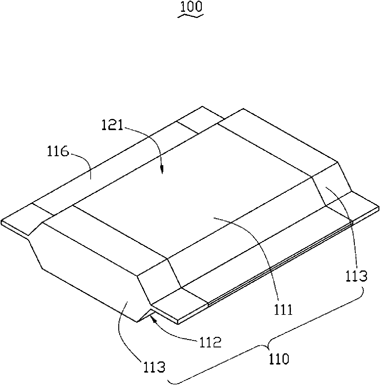
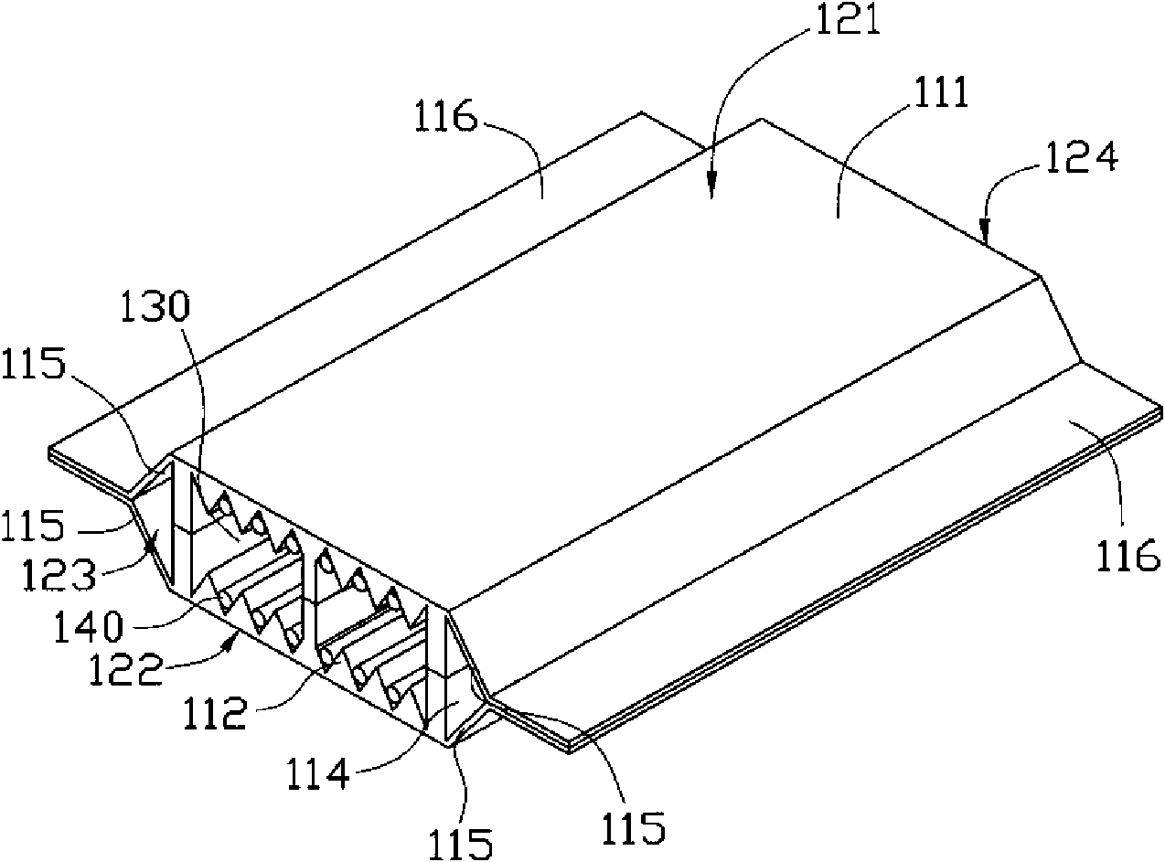
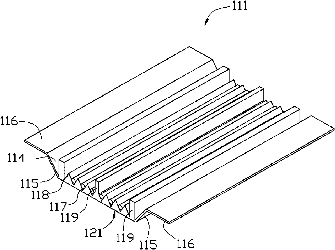
[0010] see figure 1 and figure 2 , is the heat pipe 100 provided by the present invention, which includes a heat conductor 110 , a working fluid (not shown) and a carbon nanotube array 140 .

[0011] see figure 1 and figure 2 , the heat conductor 110 is made of metal copper with good thermal conductivity, and includes a first metal cover 111 , a second metal cover 112 , and two third metal covers 113 . A groove 114 is formed in the middle of the first metal cover 111 and the second metal cover 112. The groove 114 of the first metal cover 111 is composed of a flat bottom 121 and two opposite sides 115. The groove 114 of the second metal cover 112 is composed of a flat bottom 122 and two opposite sides 115 , and two thin metal flanges 116 extend outward from the two opposite sides 115 of the groove 114 . The side of the first metal cover 111 and the seco...


PUM


Abstract

The invention provides a heat pipe, comprising a heat conductor, working fluid and a carbon nanotube array; wherein, the heat conductor comprises a first metal cover, a second metal cover and two third metal covers; the first metal cover and the second metal cover are correspondingly arranged to form a front opening end and a back opening end; the first metal cover and the second cover are respectively provided with a groove, and the opposite sides thereof are respectively extended out to form two thin metal flanges; the bottom of each groove is provided with a microchannel, and two supporting plates are arranged in each groove near the two sides; the two third metal covers are respectively buckled on the front opening end and the back opening end to form a vacuum sealing space in the heat conductor. The carbon nanotube array is fixed in the microchannel. The working fluid is filled into the heat conductor. The heat pipe of the invention uses flat metal covers internally provided with a microchannel and fixes carbon nanotube in the microchannel to increase the heat conductivity and capillary capacity and improve heat conductivity of the heat pipe.

Description

technical field [0001] The invention relates to a heat exchange device, in particular to a heat pipe. Background technique [0002] With the development of natural science and engineering technology, small electronic products such as personal computers, workstations, and handheld computers have sprung up like mushrooms after rain. In these electronic products, small heat pipes are needed to cool the heat-generating devices, so they are small in size, light in weight, and efficient. High is the most important indicator of these small heat pipes. Current heat pipes are usually in a tubular structure. Since the contact area between the tubular heat pipe and the heat source is very small, the heat dissipation efficiency is not high, so it is not suitable for the heat dissipation of such small electronic products. Some manufacturers directly flatten small tubular heat pipes to increase the contact area between the heat pipe and the heat source, but the process of flattening usua...

Claims


Application Information

Patent Timeline
Patent Type & Authority Applications(China)
IPC IPC(8): F28D15/02
Inventor 张仁淙
Owner HONG FU JIN PRECISION IND (SHENZHEN) CO LTD
Why Eureka
Try Eureka