Vibration generator for a vibration pile driver

a technology of vibration pile and vibration generator, which is applied in the direction of dynamo-electric machines, bulkheads/piles, portable percussive tools, etc., can solve the problems of pressure drop, motor torque reduction, and measurement problems, and achieve the effect of not affecting the motor torque drop

Active Publication Date: 2009-07-30
ABI ANLAGENTECHN BAUMASCHEN INDBEBEDARF
View PDF21 Cites 11 Cited by
  • Summary
  • Abstract
  • Description
  • Claims
  • Application Information

AI Technical Summary

Benefits of technology

[0008]It is therefore an object of the invention to provide a vibration generator tha

Problems solved by technology

These measures prove to be problematic, since the required drive power and the torque are dependent on the speed of rotation.
If the hydraulic drive, i.e. motor, leaves its opti

Method used


Image

  • Vibration generator for a vibration pile driver
  • Vibration generator for a vibration pile driver
  • Vibration generator for a vibration pile driver

Examples


Embodiment Construction

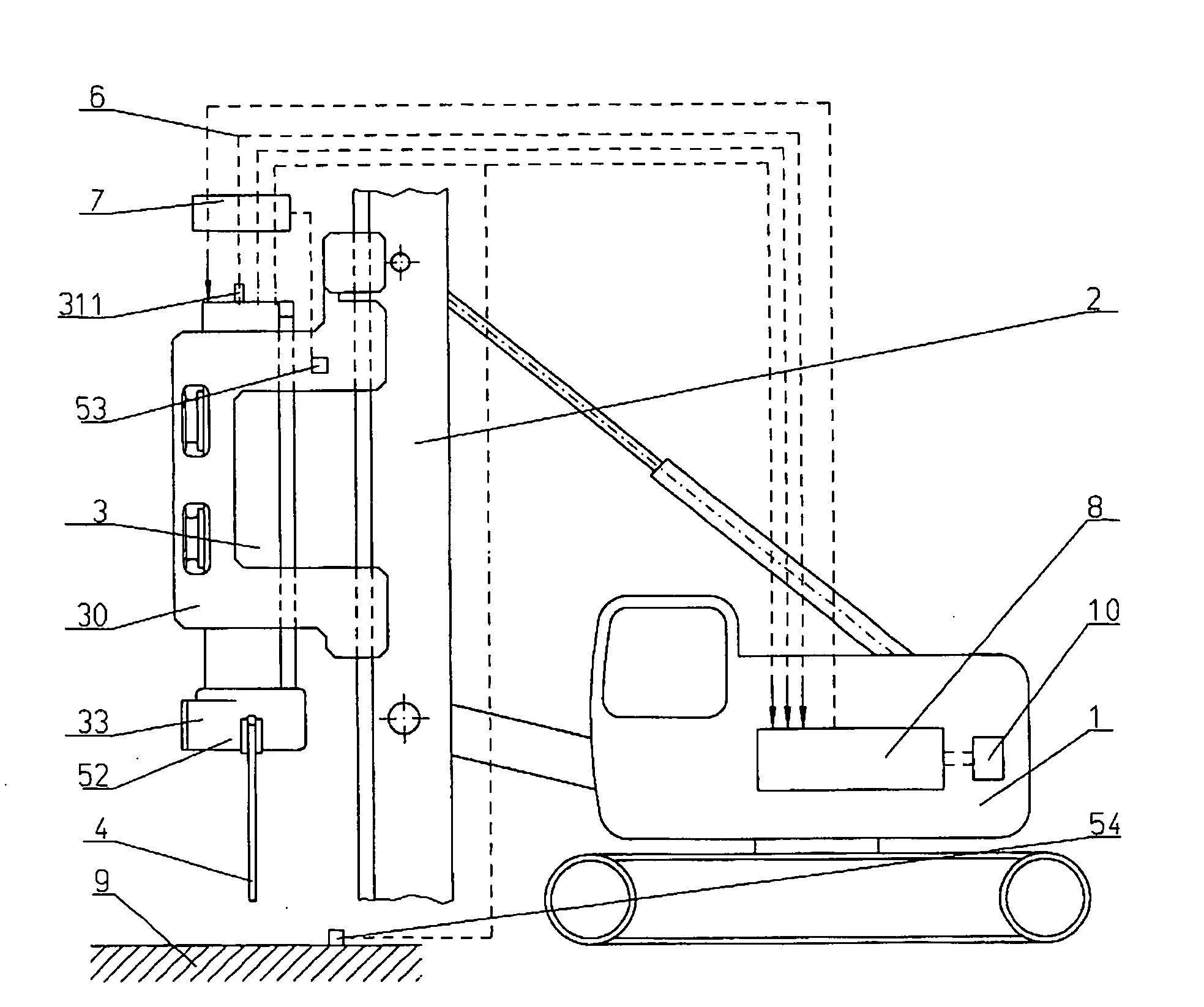
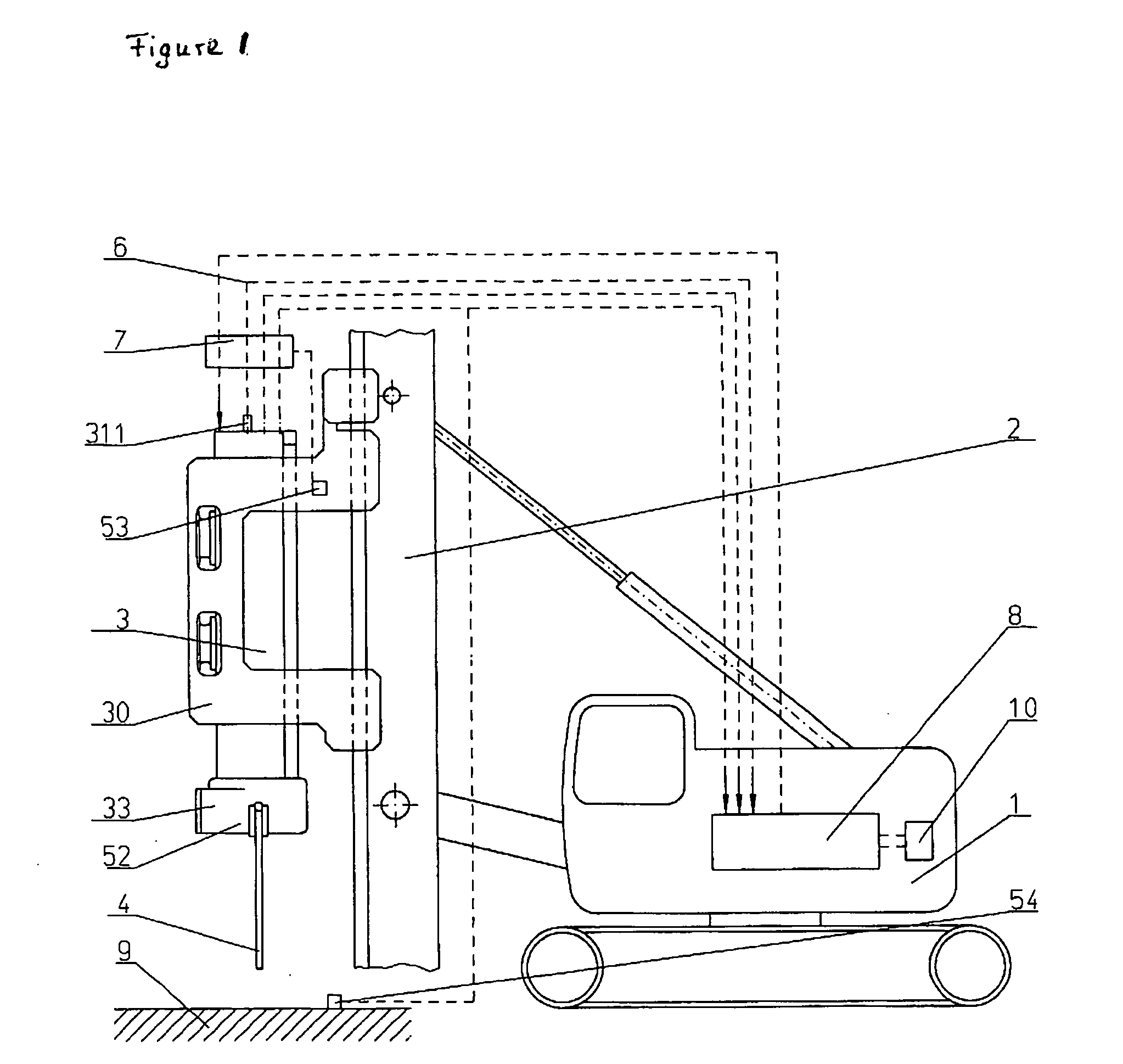
[0026]Referring now in detail to the drawings, the vibration pile driver selected as an exemplary embodiment consists essentially of a support device 1, on which a vibration generator (vibrator) 3 is disposed so that it can be displaced vertically, by way of a mast 2. Vibration generator 3 comprises a housing 31, which is surrounded by a hood 30. Clamping pliers 37 for accommodating pile-driven material 4 are disposed on hood 30. Hood 30 guides vibration generator 3, and transfers the static force of mast 2 to vibration generator 3. Vibration generator 3 generates a vibration, by way of rotating imbalances 3311, 3321, 3331, 3511, 3521, 3531, which vibration is transferred to pile-driven material 4, by way of clamping pliers 33.

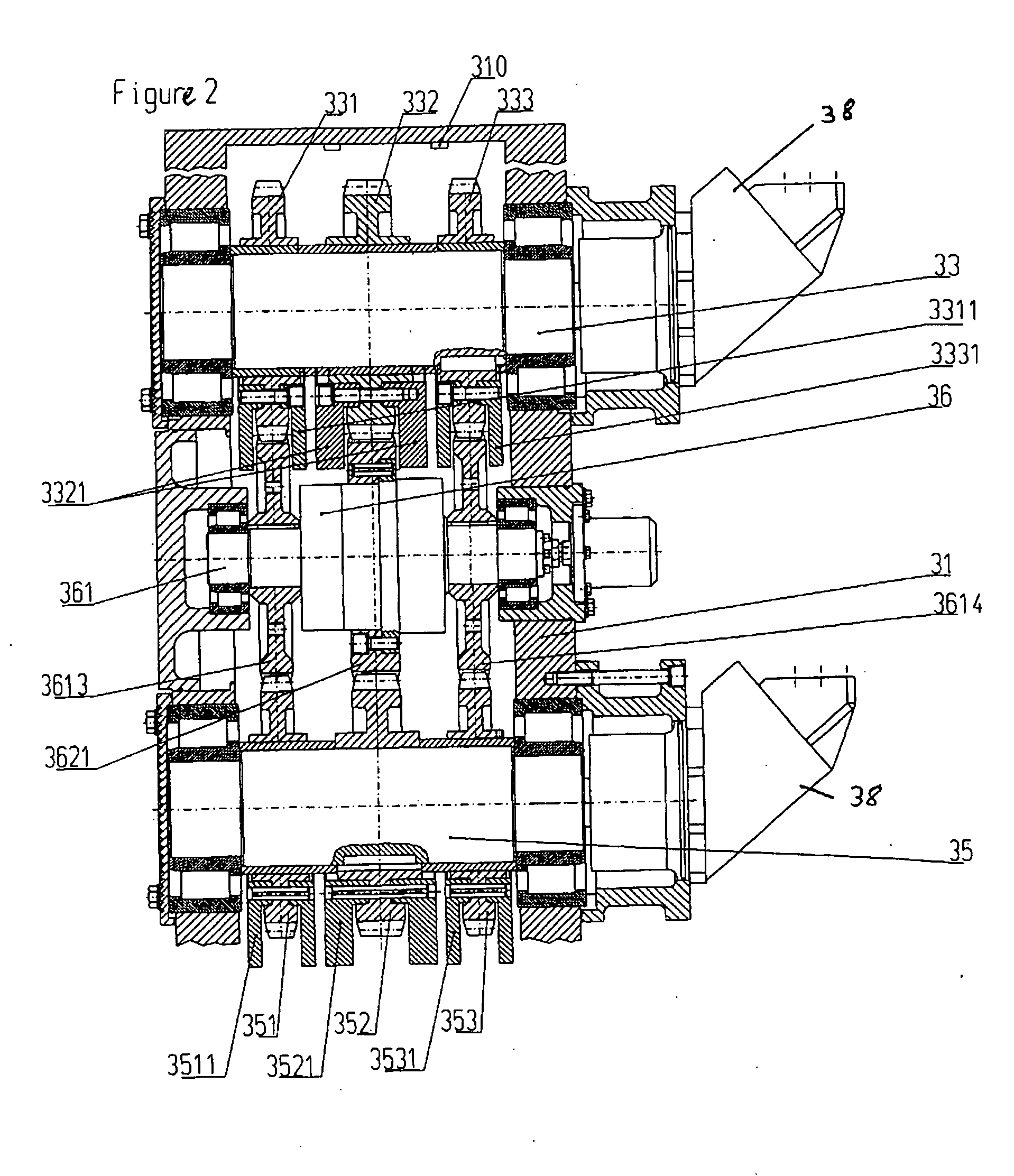
[0027]Vibration generator 3 is structured as a vibrator gear mechanism (FIG. 2). It consists essentially of a housing 31, in which shafts 33, 35 provided with gear wheels 331, 332, 333, 351, 352, 353 are mounted to rotate. Gear wheels 331, 332, 333, 351, 352, ...


PUM


Abstract

A vibration generator for a vibration pile driver, comprises imbalance masses that can rotate, which are disposed on shafts. A hydraulic drive having a changeable suction volume is disposed on the generator. A vibration pile driver consists of the vibration generator and a mast for movably supporting the vibration generator and/or an accommodation for a pile-driven material.

Description

CROSS REFERENCE TO RELATED APPLICATIONS[0001]Applicants claim priority under 35 U.S.C. §119 of European Application No. 08001601 filed Jan. 29, 2008.BACKGROUND OF THE INVENTION[0002]1. Field of the Invention[0003]The invention relates to a vibration generator for a vibration pile driver, that comprises imbalance masses that can rotate, which are disposed on shafts. A hydraulic drive having a changeable suction volume is disposed in the generator. The invention furthermore relates to a vibration pile driver having such a vibration generator.[0004]2. The Prior Art[0005]In construction, vibration generators are used to introduce objects, such as profiles, into the ground, or to draw them from the ground, or also to compact ground material. The ground is excited by vibration, and thereby achieves a “pseudo-fluid” state. The goods to be driven in can then be pressed into the construction ground by a static top load. The vibration is characterized by a linear movement and is generated by ...

Claims


Application Information

Patent Timeline
IPC IPC(8): H02K7/06E02D7/18
CPCE02D7/18B06B1/166
Inventor HEICHEL, CHRISTIANKLEIBL, ALBRECHT
Owner ABI ANLAGENTECHN BAUMASCHEN INDBEBEDARF
Why Eureka
Try Eureka