Quick release electronics platform

a technology of electronic platforms and trays, which is applied in the direction of machine supports, furniture parts, manufacturing tools, etc., can solve the problems of limited ability of known mounting platforms to provide a full range of device mounting capabilities

Active Publication Date: 2009-08-27
CARNEVALI JEFFREY D
View PDF60 Cites 55 Cited by
  • Summary
  • Abstract
  • Description
  • Claims
  • Application Information

AI Technical Summary

Problems solved by technology

However, known mounting platforms apparatus are limited in their

Method used


Image

  • Quick release electronics platform
  • Quick release electronics platform
  • Quick release electronics platform

Examples


Embodiment Construction

[0039]In the Figures, like numerals indicate like elements.

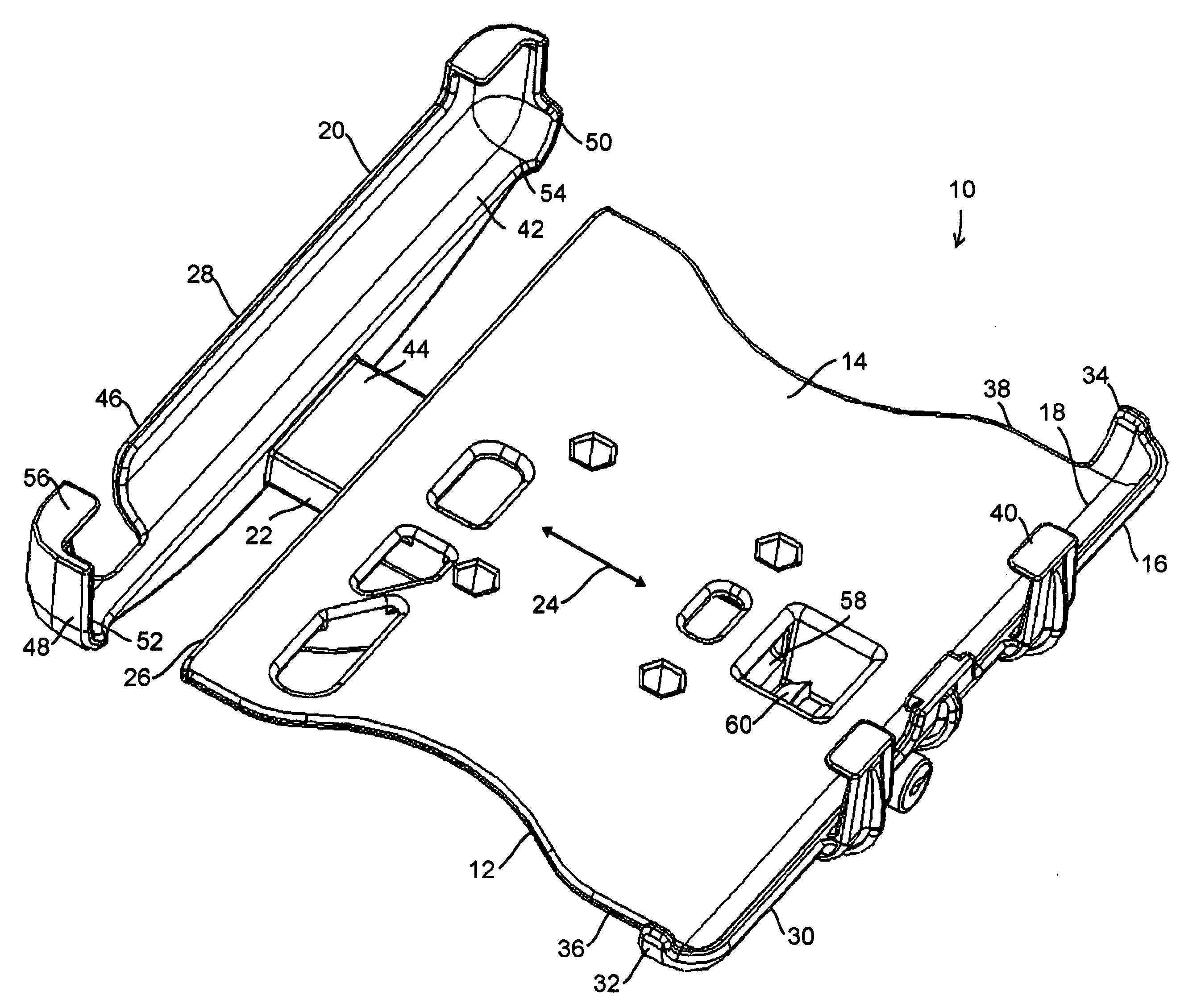
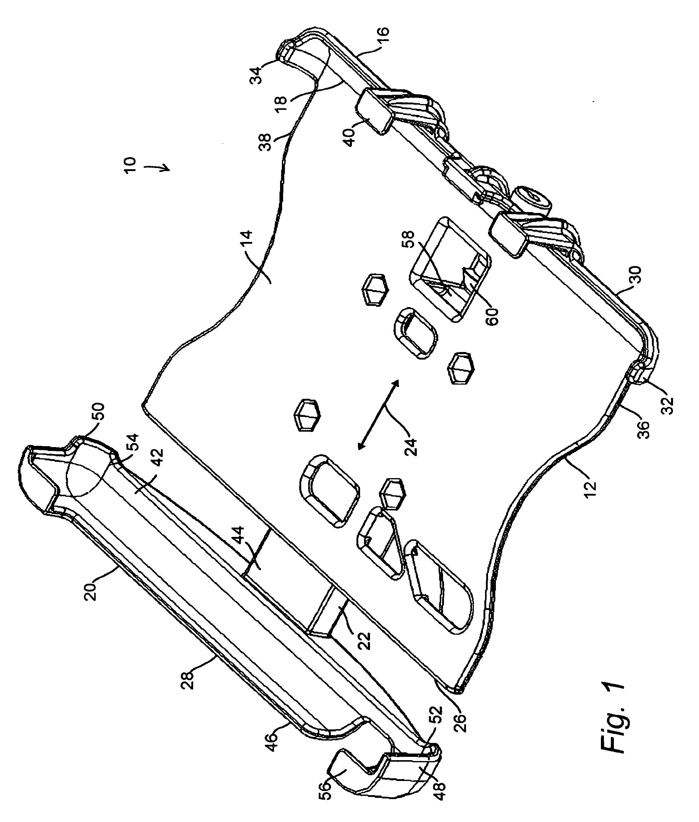
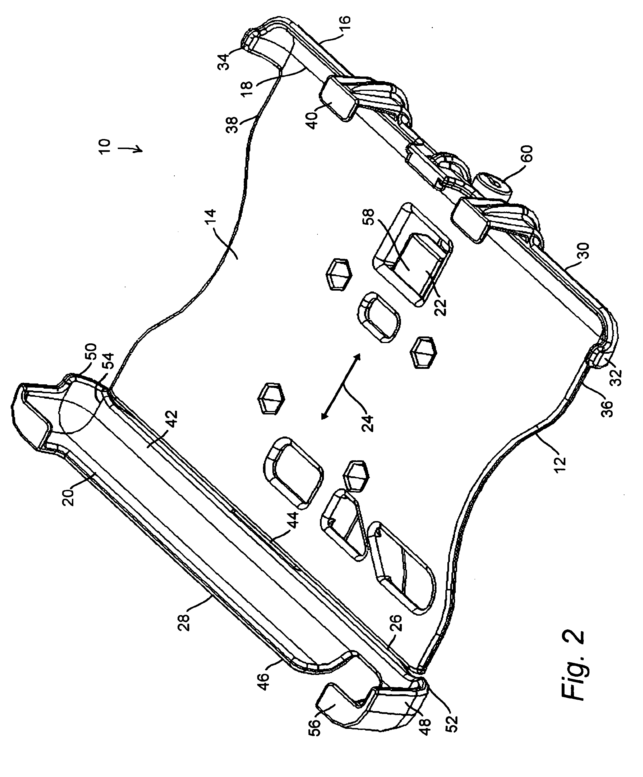
[0040]FIG. 1 illustrates the invention by example and without limitation as a novel device mounting platform apparatus 10 having a frame member 12 capable of being mounted in a vehicle and having a substantially planar device mounting surface 14 facing generally upward and a jaw portion 16 formed adjacent to one edge 18. A clamp member 20 is formed with a sled portion 22 slidably interconnected to the frame member 12 generally along a first direction (indicated by arrow 24) or a path substantially parallel therewith for extending (shown here) and retracting (shown in FIG. 2) the clamp member 20 relative to a second edge 26 of the device mounting surface 14 opposite from the first edge 18. In an expanded relationship (shown here) of the clamp member 20 relative to the frame member 12, a jaw portion 28 of the clamp member 20 is spaced along the first direction 24 away from the second edge 26 of the device mounting surface 14. ...


PUM


Abstract

A device mounting platform apparatus having a reconfigurable biasing mechanism. The device mounting platform apparatus includes a frame member capable of being mounted in a vehicle and having a device mounting surface facing generally upward. A clamp member is slidably interconnected to the frame member along a first direction. A biasing mechanism is coupled between the frame and clamp members. The biasing mechanism is reconfigurable for urging a jaw portion of the clamp member along the first direction heading either toward or away from the frame member. The biasing mechanism is thus reconfigurable for either urging the clamp member open or urging it closed.

Description

[0001]This application claims priority benefit of copending parent U.S. patent application Ser. No. 11 / 809,283 filed in the name of the inventor of the present invention on May 31, 2007, the complete disclosure of which is incorporated herein by reference.FIELD OF THE INVENTION[0002]The present invention relates generally to trays for holding portable devices, and in particular to quick release trays for holding portable electronic devices, including lap top computers and other similarly sized electronics devices.BACKGROUND OF THE INVENTION[0003]Many after-market accessories being added in automobiles and other vehicles require specially designed mounting platforms that can accommodate the limited available space normally found in a vehicle for mounting add-on equipment. These mounting platforms must be able to handle the load of the accessory device in the vibration and shock environment encountered in a moving vehicle while still permitting the portable device to be quickly and ea...

Claims


Application Information

Patent Timeline
IPC IPC(8): B60R11/00
CPCB25B5/02B25B5/06B60R11/0252B60R2011/0096B60R2011/0075B60R2011/008B60R2011/0071
Inventor CARNEVALI, JEFFREY D.
Owner CARNEVALI JEFFREY D
Why Eureka
Try Eureka