Method And Arrangement For Triggering A Series Spark Gap

a spark gap and series technology, applied in spark gap circuits, emergency protective arrangements for limiting excess voltage/current, gas-filled discharge tubes, etc., can solve the problems of further spark-over and change in the voltage of additional electrodes, and achieve the effect of protecting other components very efficiently and reliably with the spark gap

Active Publication Date: 2009-08-27
ALSTOM TECH LTD
View PDF10 Cites 23 Cited by
  • Summary
  • Abstract
  • Description
  • Claims
  • Application Information

AI Technical Summary

Benefits of technology

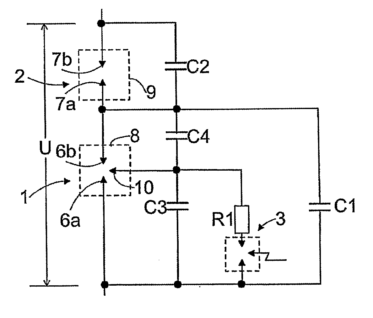
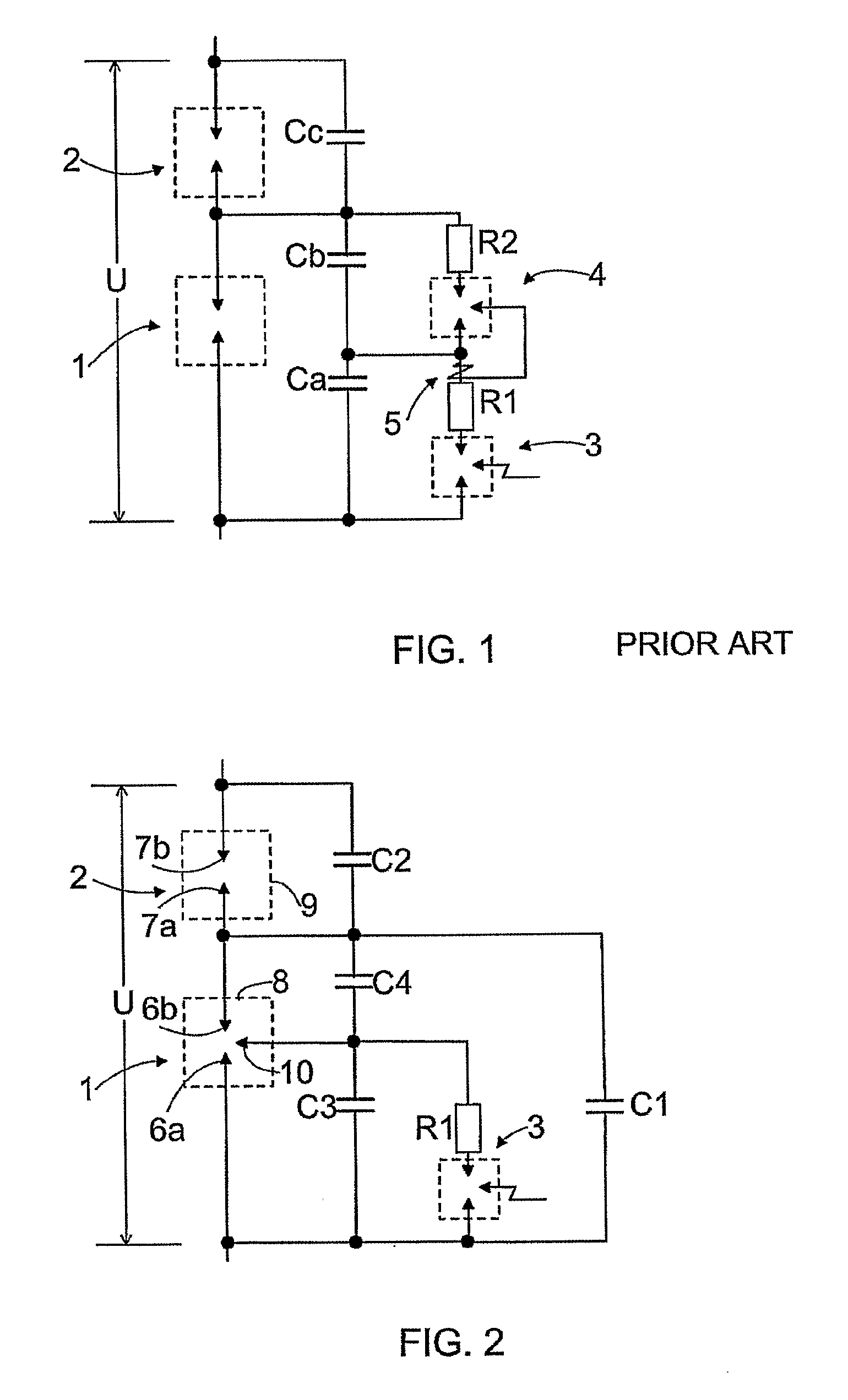
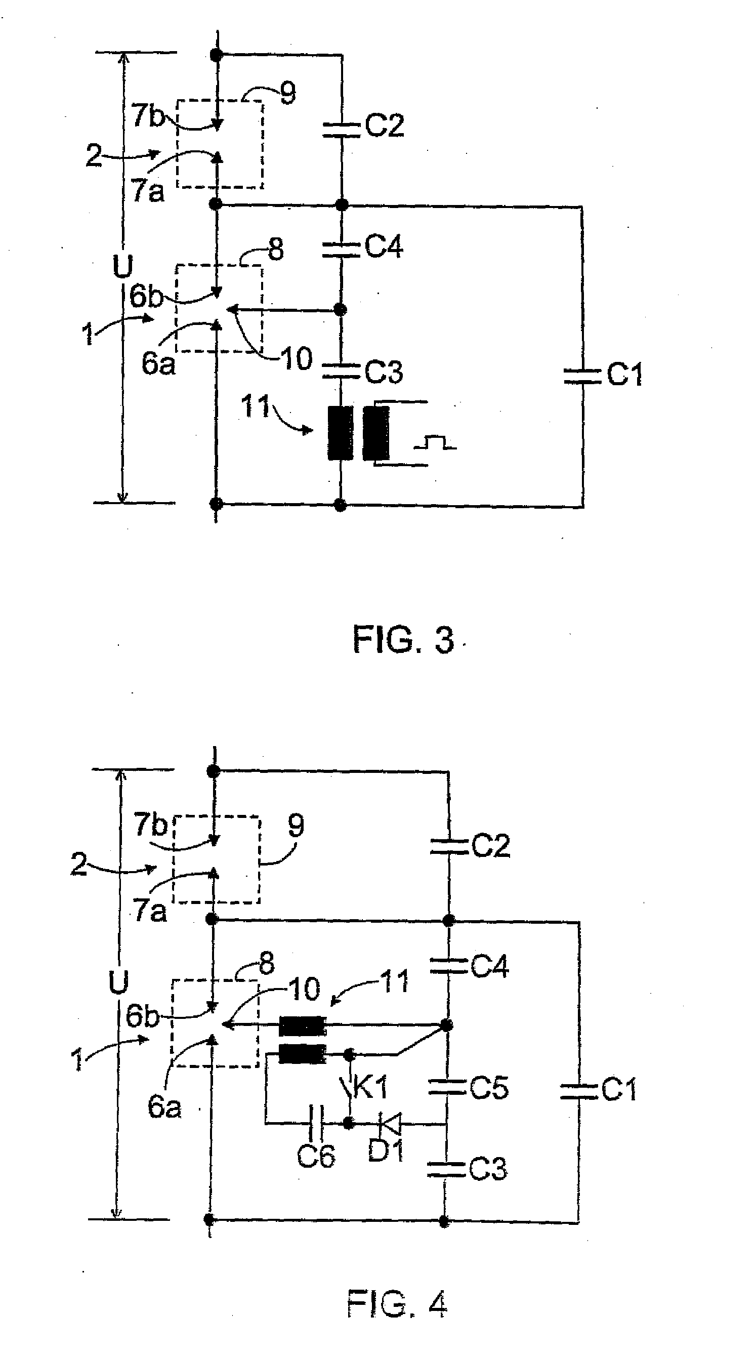
[0013]The arrangement of the invention is further characterized by comprising an additional electrode arranged in at least one partial spark gap between main electrodes thereof, second voltage distribution means for setting voltage of the additional electrode to a given level, the capacity of the second voltage distribution means being lower than the capacity of the first voltage distribution means, and means for disturbing voltage distribution of the second voltage distribution means.
[0014]The basic idea of the invention is that the arrangement comprises at least two partial spark gaps in series. In parallel with the partial spark gaps there are coupled first voltage distribution means. In at least one partial spark gap there is arranged an additional electrode whose voltage is set to a given level by means of second voltage distribution means. The voltage level of the additional electrode is changed by disturbing the voltage distribution of the second voltage distribution means. Thus the spark gap between the electrode of the partial spark gap and the additional electrode will be ignited. The capacity of the second voltage distribution means is clearly lower than the capacity of the first voltage distribution means and consequently the voltage acting over the first voltage distribution means will not change significantly. So, the voltage determined by the first voltage distribution means only acts over the spark gap which is between the second additional electrode and the electrode of the partial spark gap and which will also ignite. This leads further to the whole supply voltage acting over the second partial spark gap alone, whereby a spark-over also occurs therein. The disclosed solution permits ignition of the partial spark gaps with voltage that is considerably lower than their autoignition voltage. Consequently it is possible to protect other components very efficiently and reliably with the spark gap. The basic idea of one embodiment is that voltage distribution of voltage distribution means is disturbed by short-circuiting a gap between poles of one voltage distribution means in the second voltage distribution means, for instance, by means of a gas-pressure spark gap, i.e. a trigatron. The basic idea of a second embodiment is that voltage distribution of others is disturbed by feeding a current pulse by means of a pulse transformer. This leads to a change in the voltage of the additional electrode and further to a spark-over.

Problems solved by technology

This leads to a change in the voltage of the additional electrode and further to a spark-over.

Method used


Image

  • Method And Arrangement For Triggering A Series Spark Gap
  • Method And Arrangement For Triggering A Series Spark Gap
  • Method And Arrangement For Triggering A Series Spark Gap

Examples


Embodiment Construction

[0021]FIG. 2 shows a solution, in which a main spark gap is divided into two partial spark gaps in series, i.e. into a first partial spark gap 1 and a second partial spark gap 2. In parallel with the first partial spark gap there is coupled a capacitor C1. In parallel with the second partial spark gap there is coupled a capacitor C2. These so-called first capacitors C1 and C2 are designed in this example such that in a normal situation they distribute the voltage in equal amounts over each one of the partial spark gaps 1 and 2.

[0022]In the first partial spark gap 1 there are main electrodes 6a and 6b in a manner known per se. Correspondingly, in the second partial spark gap 2 there are main electrodes 7a and 7b. Further, the first partial spark gap 1 is arranged in a housing 8. The second partial spark gap 2 is also arranged in a housing 9 in a manner known per se.

[0023]Apart from the main electrodes 6a and 6b there is an additional electrode 10 in the first partial spark gap 1. The...


PUM


Abstract

A series spark gap is triggered such that in parallel with partial spark gaps (1, 2) of the series spark gap there are coupled first voltage distribution means. Further, at least in one partial spark gap (1, 2) there is arranged an additional electrode (10) whose voltage is set to a given level by means of second voltage distribution means. The voltage level of the additional electrode (10) is changed by disturbing the voltage distribution of the second voltage distribution means. Thus the spark gap between the main electrode (6a, 6b) of the partial spark gap (1) and the additional electrode (10) will be ignited. Capacity of the second voltage distribution means is lower than that of the first voltage distribution means and consequently the voltage acting over the first voltage distribution means does not change significantly. Thus the voltage determined by the first voltage distribution means acts over the spark gap that is between the additional electrode (10) and the second main electrode (6a, 6b) of the partial spark gap (1) and that will also ignite, which further results in the supply voltage (U) acting only over the second partial spark gap (2), whereby a spark-over will also occur therein.

Description

BACKGROUND OF THE INVENTION[0001]The invention relates to a method for triggering a series spark gap, in which there are in series at least two partial spark gaps, and supply voltage is distributed over the partial spark gaps by means of first voltage distribution means.[0002]The invention also relates to an arrangement for triggering a series spark gap, the series spark gap comprising at least two partial spark gaps in series, and the arrangement comprising first voltage distribution means for distributing supply voltage over the partial spark gaps.[0003]For instance, in connection with high-voltage lines there are employed series capacitor batteries to compensate for line inductance. In parallel with the capacitor battery, in protection thereof, there is generally coupled a metal oxide varistor and / or a spark gap. The current-voltage characteristic of the metal oxide varistor is highly non-linear and as battery current rises, the metal oxide varistor limits capacitor voltage. A ty...

Claims


Application Information

Patent Timeline
Patent Type & Authority Applications(United States)
IPC IPC(8): H02H7/16H01TH01T2/02H01T15/00
CPCH01T15/00H01T2/02
Inventor HALLSTROM, JARIKANSALA, TARMOHOLM, HEIKKI
Owner ALSTOM TECH LTD
Why Eureka
Try Eureka