Carrier and Backhoe Control System and Method

a control system and backhoe technology, applied in the field of power machines, can solve the problems of little or no climate control of the immediate operator area, reducing the visibility of the work area, and allowing for enclosed cab operation, so as to increase the user's adjustability of the functions availabl

Active Publication Date: 2009-08-27
CLARK EQUIP CO INC
View PDF36 Cites 18 Cited by
  • Summary
  • Abstract
  • Description
  • Claims
  • Application Information

AI Technical Summary

Benefits of technology

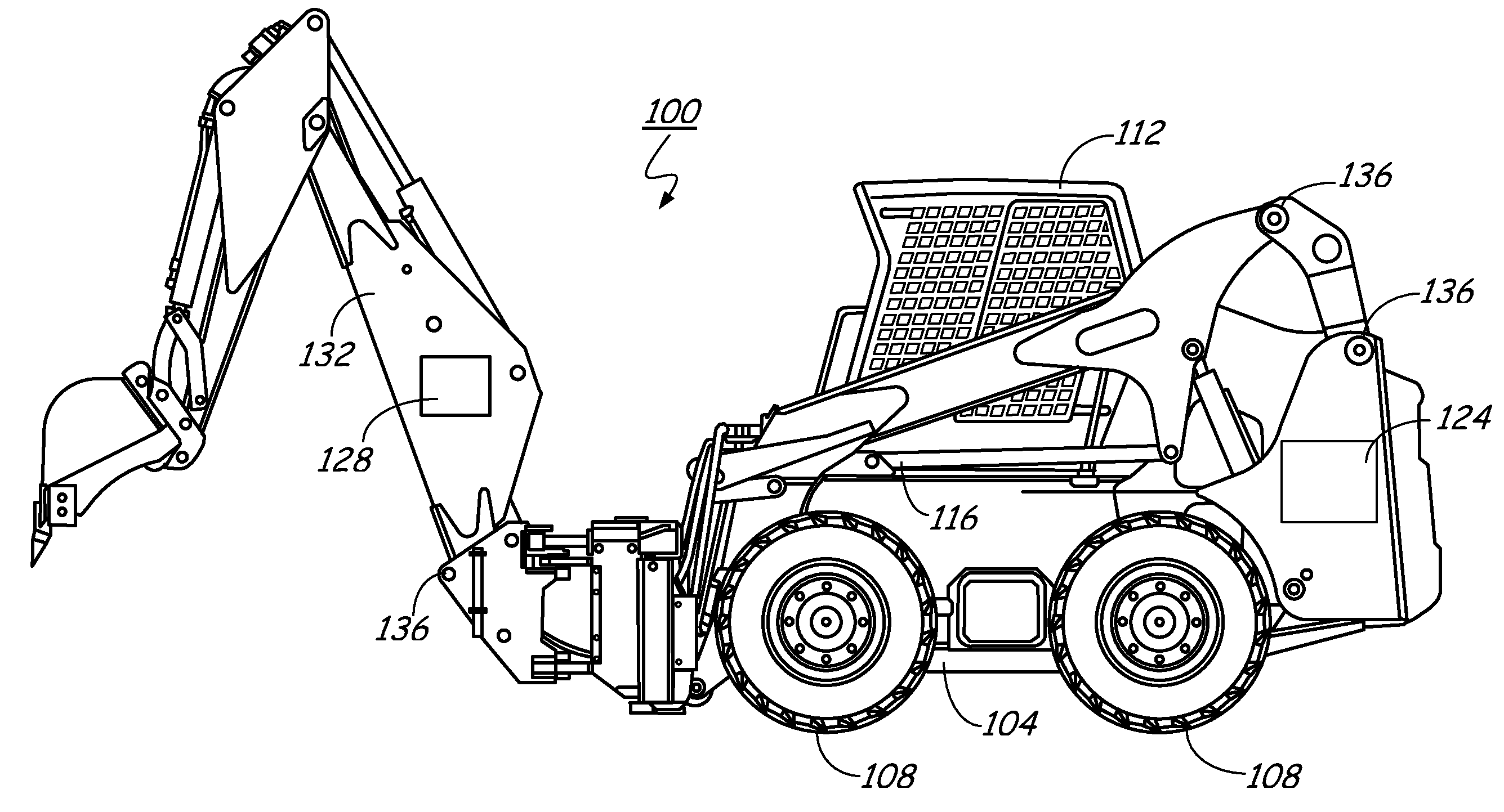
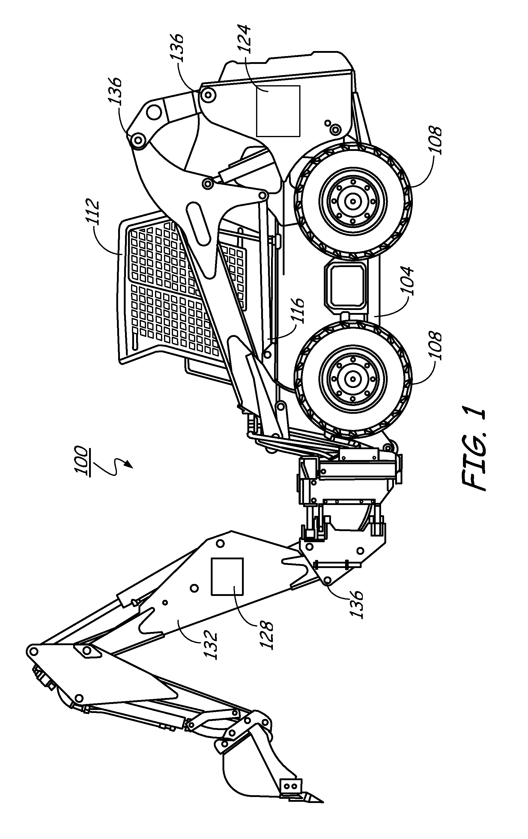
[0007]In one embodiment, the invention provides a control system that operates an attachment, such as a backhoe, using controls available in a carrier. The control system allows an operator to use the attachment from inside a protective area of a cab with all cab enclosures installed, provides interaction between the carrier and the attachment, and increases user adjustability of functions available by the attachment.

Problems solved by technology

This does not allow for enclosed cab operation, resulting in little if any climate control of the immediate operator area.
This can also drastically reduce work area visibility due to the control system positioning.

Method used


Image

  • Carrier and Backhoe Control System and Method
  • Carrier and Backhoe Control System and Method
  • Carrier and Backhoe Control System and Method

Examples


Embodiment Construction

[0016]Before any embodiments of the invention are explained in detail, it is to be understood that the invention is not limited in its application to the details of construction and the arrangement of components set forth in the following description or illustrated in the following drawings. The invention is capable of other embodiments and of being practiced or of being carried out in various ways. Also, it is to be understood that the phraseology and terminology used herein is for the purpose of description and should not be regarded as limiting. The use of “including,”“comprising,” or “having” and variations thereof herein is meant to encompass the items listed thereafter and equivalents thereof as well as additional items. Unless specified or limited otherwise, the terms “mounted,”“connected,”“supported,” and “coupled” and variations thereof are used broadly and encompass both direct and indirect mountings, connections, supports, and couplings. Further, “connected” and “coupled”...


PUM


Abstract

A power machine includes a carrier comprising a supporting frame, an operator compartment and a joystick controller disposed in the operator compartment and configured to generate movement signals in response to operator movement of the joystick controller. An attachment is detachably coupled to the power machine. A carrier control unit is disposed on the carrier and configured to receive the movement signals from the joystick controller. An attachment control unit is disposed on the attachment and configured to control movement of the attachment. A network is coupled to the carrier control unit and to the attachment control unit and is configured to carry instructions from the carrier control unit to the attachment control unit. A state selection input is disposed in the operator compartment to select one of at least two operational states including a carrier state and an attachment state. In the carrier state, the carrier control unit is configured to control operation of the carrier in response to operator movement of the joystick controller. In the attachment state, the attachment control unit is configured to control operation of the attachment in response to operator movement of the joystick controller.

Description

CROSS-REFERENCE TO RELATED APPLICATION[0001]The present application is based on and claims the benefit of U.S. provisional patent application Ser. No. 61 / 031,121, filed Feb. 25, 2008, the content of which is hereby incorporated by reference in its entirety.FIELD OF THE INVENTION[0002]Embodiments of the invention generally relate to power machines, and more specifically, to a control system for use with power machines.BACKGROUND OF THE INVENTION[0003]Power machines, such as skid steer loaders, typically include one or more machine controllers that control the power machines in response to physical inputs from an operator. The machine controllers can include, for example, a carrier controller and an attachment controller. For control of many types of attachments, for instance a backhoe attachment for a skid steer loader or other type of power machine carrier, separate sets of operator controls are used to control the carrier (power machine) and the attachment.[0004]In some conventiona...

Claims


Application Information

Patent Timeline
Patent Type & Authority Applications(United States)
IPC IPC(8): G06F19/00
CPCE02F3/3695E02F9/2004G05B2219/23083G05B19/106E02F9/26
Inventor MINDEMAN, SPENCER L.HIRSCHKORN, DORAN D.LOUGHEED, CHRISTOPHER W.BOGNER, PHILLIP D.LIEBEL, ALVIN A.
Owner CLARK EQUIP CO INC
Why Eureka
Try Eureka