
Inkjet printing apparatus and inkjet printing method

a technology of inkjet printing and printing apparatus, which is applied in the field of inkjet printing apparatus and inkjet printing method, can solve the problems of inadequacies, inadequacies, and uneven ink density in the form of white stripes,

Active Publication Date: 2009-09-03
CANON KK
View PDF4 Cites 14 Cited by
  • Summary
  • Abstract
  • Description
  • Claims
  • Application Information

AI Technical Summary

Benefits of technology

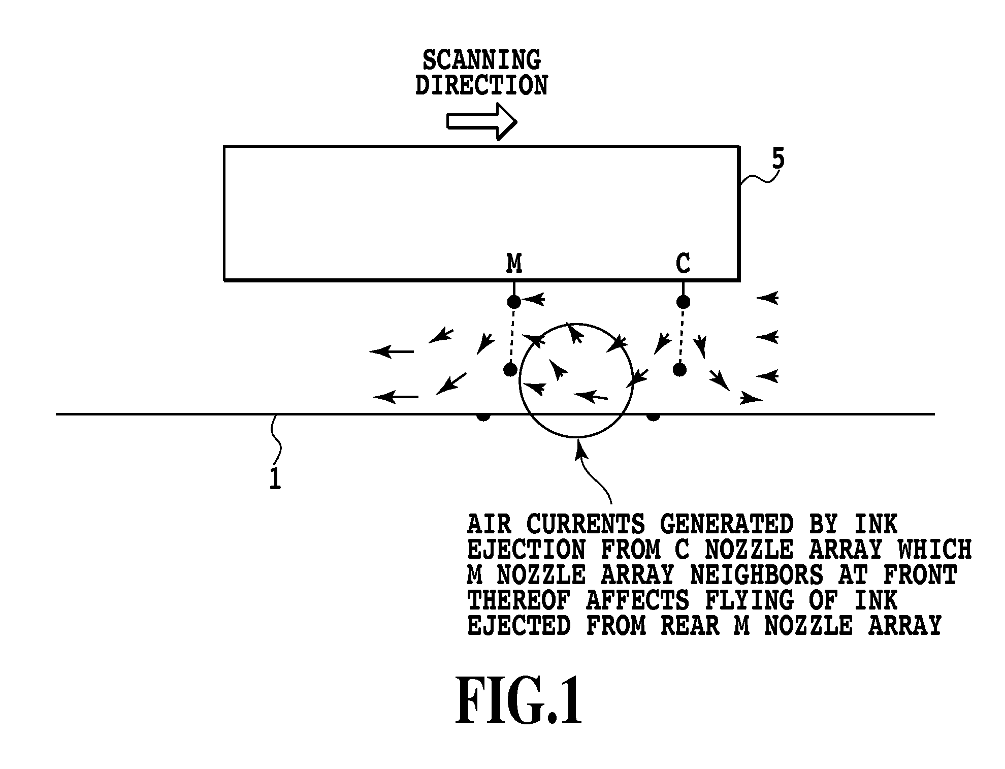
[0013]An object of the present invention is to provide an inkjet printing apparatus and an ink jet printing method which are capable of reducing the a stripe at a joining portion in consideration of how end deviation is affected by air currents caused by other ejection opening arrays.
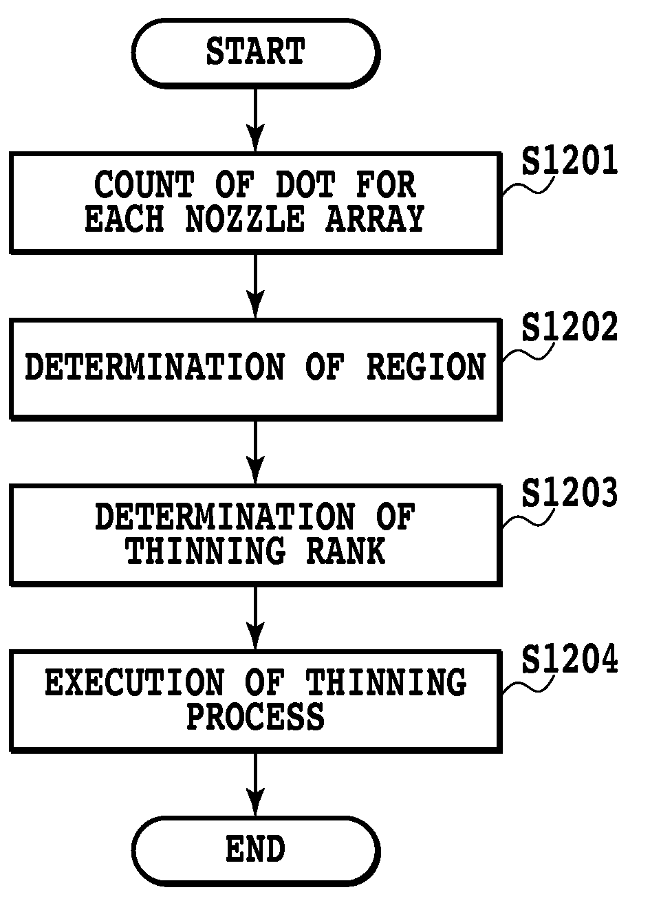
[0016]According to the above-described configuration, when thinning processing is performed to reduce a black stripe to be caused by making an overlap between scanning areas which is designed to prevent an end deviation from causing a white stripe, the thinning processing targeting for one ejection opening array is performed in consideration of not only a printing duty of the target ejection opening array, but also a printing duty of another adjacent ejection opening arrays. Accordingly, thinning processing can be performed which accurately reflects an amount of actual end deviation that occurs due to air currents caused by ink ejection not only from the target ejection opening array but also the adjacent ejection opening array. As a result, a good reduction of the stripes at a joining portion is possible.

Problems solved by technology

At a boundary between unit areas in each of which a printed image is completed in a single scan or multiple scans, ink density unevenness in the form of a white stripe may be caused, especially when a density of ink ejected from a print head (print duty) is high.
Accordingly, thinning processing performed to prevent the occurrence of the black stripe caused by an overlap between image completing areas, in the case that a printing duty is low and therefore the end deviation does not occur, may not be appropriate.
As described above, if the thinning processing on printing data for a joining portion (overlapping region) is preformed according to a printing duty of only one of the ejection opening arrays, as described in Japanese Patent Laid-Open No. 2004-168003, also in the case where multiple ejection opening arrays are arranged next to each other, the resultant thinned-out printing data is unsuitable for an amount of end deviation which actually occurs.
As a result, it is impossible to perform high-quality printing dealing with the end deviation with high accuracy.

Method used


Image

  • Inkjet printing apparatus and inkjet printing method
  • Inkjet printing apparatus and inkjet printing method
  • Inkjet printing apparatus and inkjet printing method

Examples


first embodiment

[0048]A print head according to a first embodiment of the present invention has 512 ejection openings (nozzles) at a density of 1200 ejection openings per 1 inch (1200 dpi) for one color of ink. In the case of one-pass printing, a conveying amount of a printing medium is (512 / 1200) inches≈10.84 (mm), while, in the case of N-pass printing, it is a conveying amount obtained by dividing the number of 512 ejection openings by N. In other words, in N-pass printing, 10.84 / N (mm), which is obtained by dividing the conveying amount in one-pass printing by N, is a normal paper conveying amount for a single scan.

[0049]In both cases of one-pass and multi-pass printing, an only slight error may occur in a conveying operation by a paper conveying mechanism. However, when an end deviation, which is a target of the present embodiment, occurs, even in an ideal state in which there is no above-described error, it is impossible to obtain continuous images across a boundary between former scanning are...

second embodiment

[0087]The present invention can also be applied to the case of using a so-called full-line head in which nozzles are arranged in accordance with the width of a printing medium to be conveyed. FIG. 17 is a view illustrating an example of such a full-line head. The full-line head illustrated in the drawing is constituted by arranging multiple chips, in which nozzle arrays of respective C, M, Y, and K are arranged, so as to form an overlapping part. In the drawing, only four chips are illustrated for simplification.

[0088]In the inkjet printing apparatus, a printing medium is to be conveyed in a predetermined direction relative to a print head in which a plurality of head chips having multiple ejection opening arrays formed by arranging multiple ink ejection openings (nozzles), the plurality of chips being arranged so that some of the ejection openings overlap each other in the predetermined direction.

[0089]Also in a configuration using such a full-line head, due to conveying of a print...


PUM


Abstract

When thinning processing is performed to reduce the occurrence of black stripe caused by an overlap between scanning areas that is designed to prevent an end deviation from causing a white stripe, dots printed in a predetermined region by not only an ejection opening array subjected to the thinning processing but also other ejection opening arrays are counted so as to obtain their respective printing duties. Then, a color gamut is obtained based on the printing duties of the respective ejection opening arrays. Then, a thinning rate of the ejection opening array subjected to thinning processing is obtained by referring to a table corresponding to the color gamut, based on the printing duties of the respective ejection opening arrays obtained as above, and the thinning processing is performed. Accordingly, thinning processing can be performed which accurately reflects an amount of actual end deviation.

Description

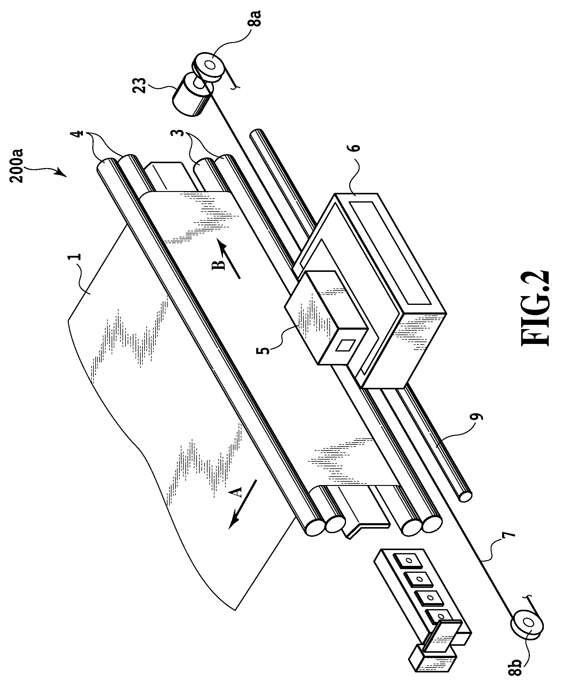
BACKGROUND OF THE INVENTION[0001]1. Field of the Invention[0002]The present invention relates to an inkjet printing apparatus and an inkjet printing method, and particularly relates to reduction of density unevenness, such as so-called joint stripe, which arises from a phenomenon in which an ink ejecting direction is deviated at a boundary between scanning areas of a print head.[0003]2. Description of the Related Art[0004]Heretofore, various image forming apparatuses for printing an image on a printing medium such as a paper sheet and an OHP sheet have been proposed as types in each of which a print head in any of various printing systems is provided. The print heads are available in a wire dot system, a thermal system, a thermal transfer system, an inkjet system, or the like. Especially, the inkjet system has been attracting attention as a system that is low in running cost and is capable of carrying out a highly silent printing operation because the system directly send inks to a ...

Claims


Application Information

Patent Timeline
Patent Type & Authority Applications(United States)
IPC IPC(8): B41J29/38
CPCG06K15/105H04N1/6019G06K2215/0094
Inventor MASUYAMA, ATSUHIKO
Owner CANON KK
Learn More