Gate-driver IC with HV-isolation, especially hybrid electric vehicle motor drive concept

Active Publication Date: 2009-10-01
INFINEON TECH AMERICAS
View PDF6 Cites 32 Cited by
  • Summary
  • Abstract
  • Description
  • Claims
  • Application Information

AI Technical Summary

Benefits of technology

[0034](j) There are reduced space requirements, reduced complexity of the circuit and reduced cost.
[0035]The invention can be used in numerous applications in the power management market, especially motor drive applications like hybrid electric vehicle traction motors

Problems solved by technology

These applications have high current carrying requirements in a minimum space, challenging state-of the art power modules in terms of achievable power density.
Then, even 42V was not enough to keep the phase currents of those high power motors and applications to a reasonable order of magnitude.
The existence of a high voltage system in HEVs causes a major challenge: the 12V powered systems need to be well protected from the high voltage system since standard automotive blocking and protection circuits are not dimensioned to withstand more than 30V or 40V.
Even the known 42V system specifications do not allow more than 60V in the entire power net due to safety reasons.
Otherwise the LV components would immediately be destroyed by accidental direct contact to the HV net.
Thus, while the 12V battery was relatively safe and not life threatening; an accidental contact to the new HV power net can be deadly.
This isolation problem between the LV and HV bus is quite complicated since the two electric circuits in a car still need to communicate with each other.
It has been very difficult to establish such a high isolation w

Method used


Image

  • Gate-driver IC with HV-isolation, especially hybrid electric vehicle motor drive concept
  • Gate-driver IC with HV-isolation, especially hybrid electric vehicle motor drive concept
  • Gate-driver IC with HV-isolation, especially hybrid electric vehicle motor drive concept

Examples


Example

DETAILED DESCRIPTION OF THE DRAWINGS

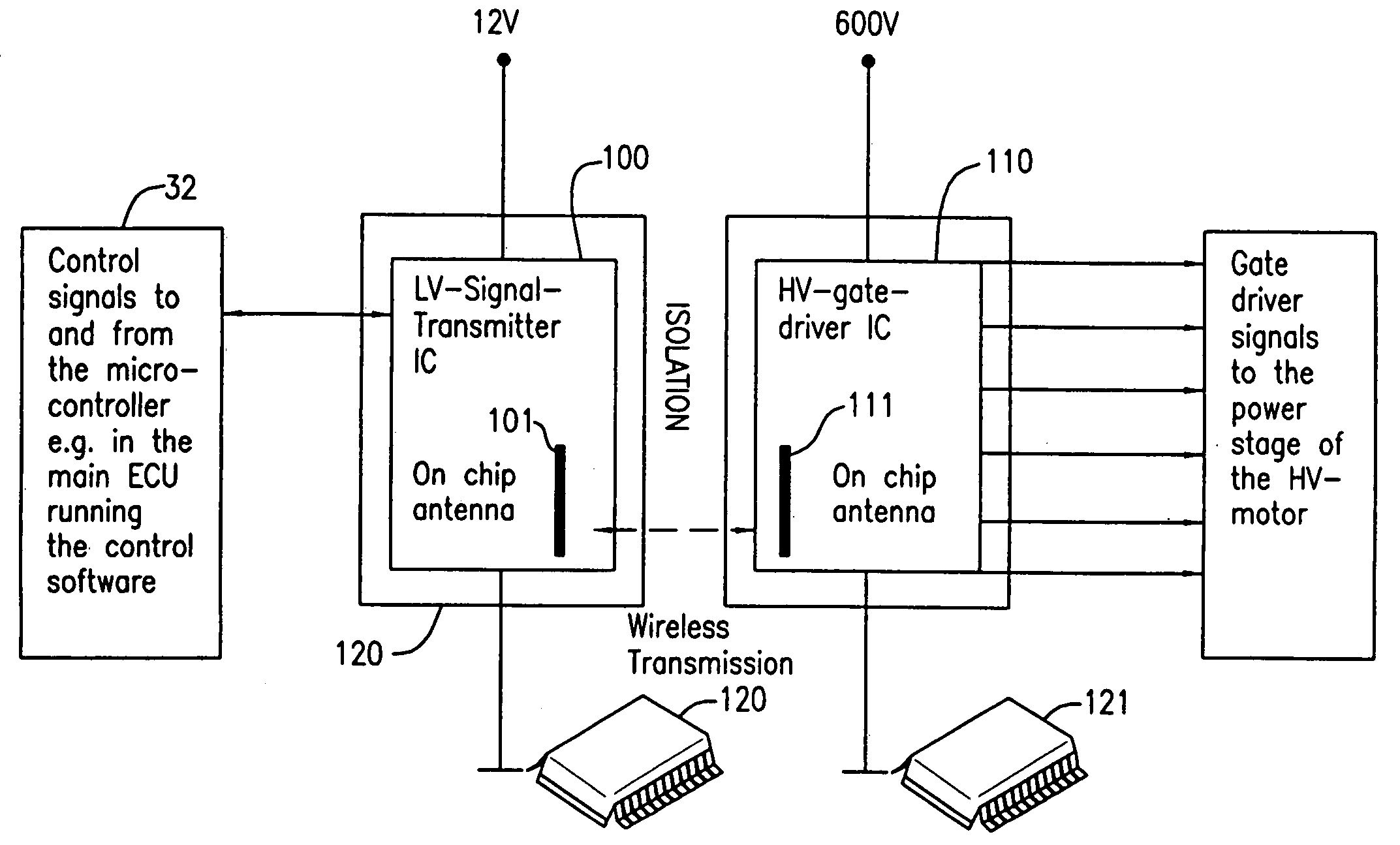
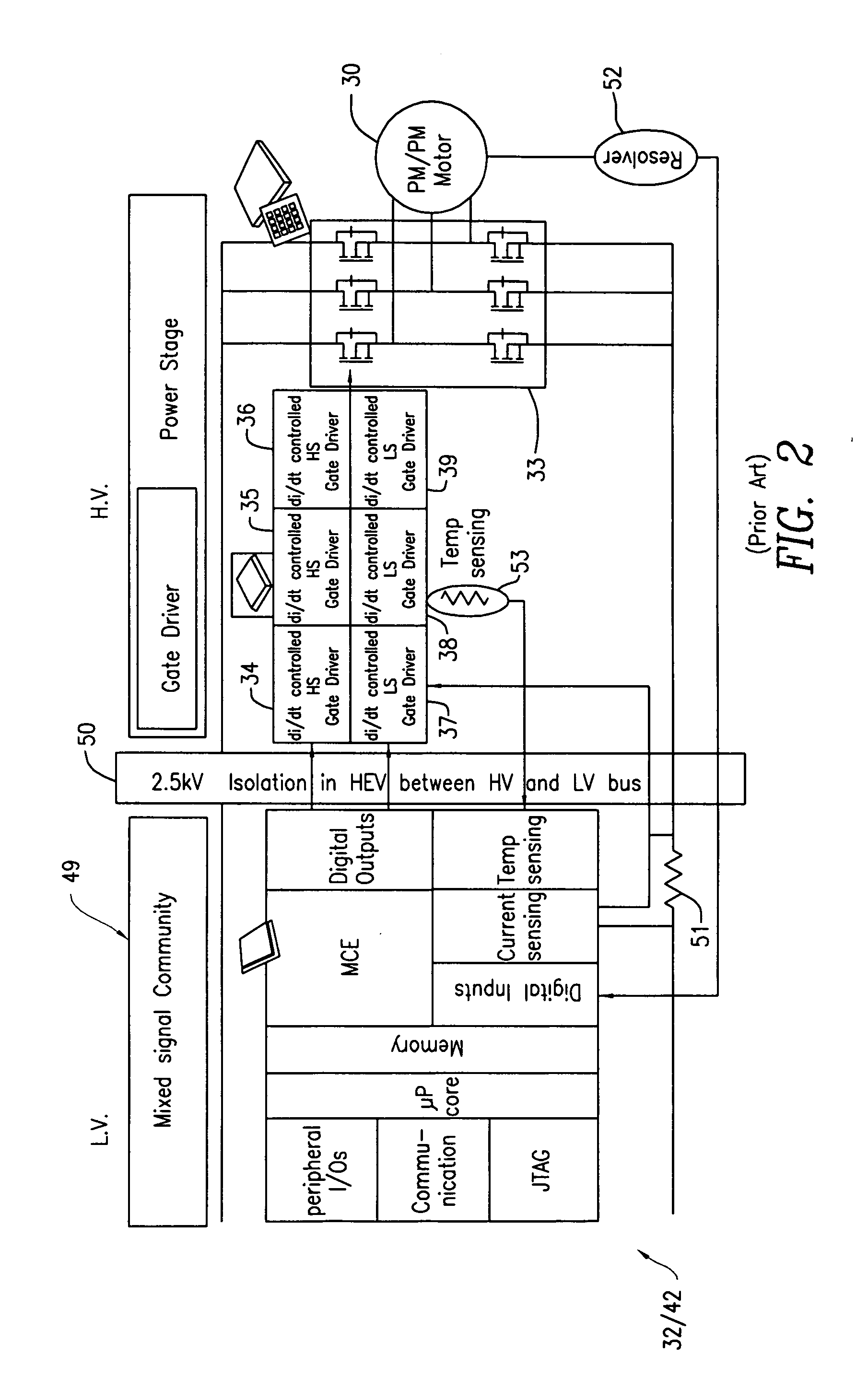
[0046]Referring first to FIG. 3, which shows the structure of copending application Ser. No. 12 / 009,721 (IR-3522), there is shown a first semiconductor IC chip 100 which is the LV signal transmitter IC of FIG. 2, adapted however with an on chip antenna 101. Control signals from control circuit 32 / 49 of FIG. 2 in the 12 volt network running the control software drives IC 100 which would be the left hand side of barrier 50 in FIG. 2. A spaced HV gate driver IC 110 also having an on-chip antenna 111 is spaced from IC by a distance of, for example, 5 millimeters or as needed to provide the full isolation between the LV and HV networks and would be on the right hand side of barrier 50 in FIG. 2. The IC 110 then provides the necessary gate driver signals to the power stage of the HV motor 30, for example, drivers 34 to 39 of FIG. 2 the current and temperature sensors and the like. The barrier 50 of FIG. 2 then consists of the physical gap between ICs 10...


PUM


Abstract

An automotive drive system for a high voltage electric motor comprises a microcontroller and ECU powered by a low voltage (12 volt) bus net which controls the drives of a high voltage inverter powered by a 100 volt or higher source, which, in turn, drives the motor. To provide good electrical insulation between the low voltage and high voltage systems, the low voltage control signals are produced by a low voltage signal input chip which has a bottom electrode which produces a control potential responsive to the ECU output and a high voltage driver IC which drives the power devices of the high voltage inverter. The high voltage driver IC has a top electrode which drives the high voltage IC function. The bottom electrode of the LV input chip is coupled to the top electrode of the high voltage driver IC through an insulation layer, defining a capacitive coupler which defines an isolation barrier between the low voltage net and the high voltage system insulation. The two ICs may be bare chips, individually packaged chips or co-packed chips. Plural control IC chips and driver IC chips can communicate with one another for diverse control functions, including “smart” functions.

Description

RELATED APPLICATIONS[0001]This application is related to copending application Ser. No. 11 / 676,029, filed Feb. 16, 2007 in the name of Michael A. Briere (IR-2724) and copending application Ser. No. 12 / 009,721, filed Jan. 22, 2008 in the name of Henning Hauenstein (IR-3522) each of which are assigned to the assignee of this application.FIELD OF THE INVENTION[0002]This invention relates to the drive of high voltage semiconductor circuits from a low voltage integrated circuit with high voltage insulation between the two circuits.BACKGROUND OF THE INVENTION[0003]There is an increasing demand for the management of high currents in a very small space and in harsh environments exposed to large temperature changes. Thus, in the automotive sector, due to increasing electrification functions, the high current demand increases enormously as for inverter and E-motor drives in hybrid car applications, starter-generator applications, and high power DC / DC converters or x-by-wire applications used ...

Claims


Application Information

Patent Timeline
IPC IPC(8): H02H9/00
CPCH01L25/16H01L2223/6677H02M7/003H03K17/689H01L2224/4813H01L2924/13055H01L2924/13091H01L2924/10253H01L2924/00
Inventor HAUENSTEIN, HENNING M.
Owner INFINEON TECH AMERICAS
Why Eureka
Try Eureka