Curtain Fixing Device

Inactive Publication Date: 2016-03-17
CHENG LI MING
View PDF0 Cites 3 Cited by
  • Summary
  • Abstract
  • Description
  • Claims
  • Application Information

AI Technical Summary

Benefits of technology

[0008]An objective of the present invention is to provide a curtain fixing device that has a simpl

Problems solved by technology

Since the left bracket 93 and the right bracket 94 extend in three dimensions and, thus, have a complicated structure, the left bracket 93 and the right bracket 94 have difficulties in formation and are not easy to manufacture while requiring a larger spac

Method used


Image

  • Curtain Fixing Device
  • Curtain Fixing Device
  • Curtain Fixing Device

Examples


Embodiment Construction

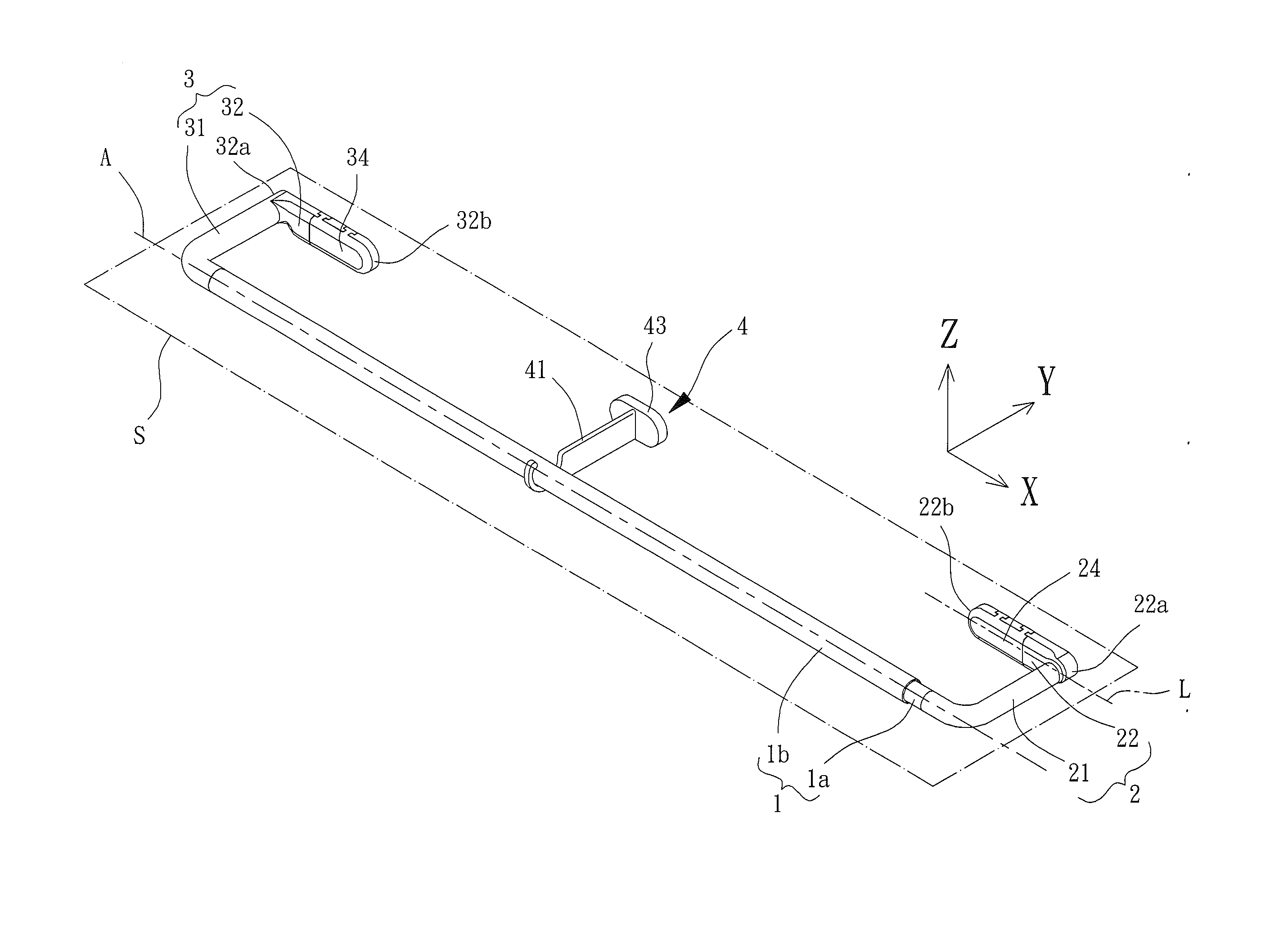
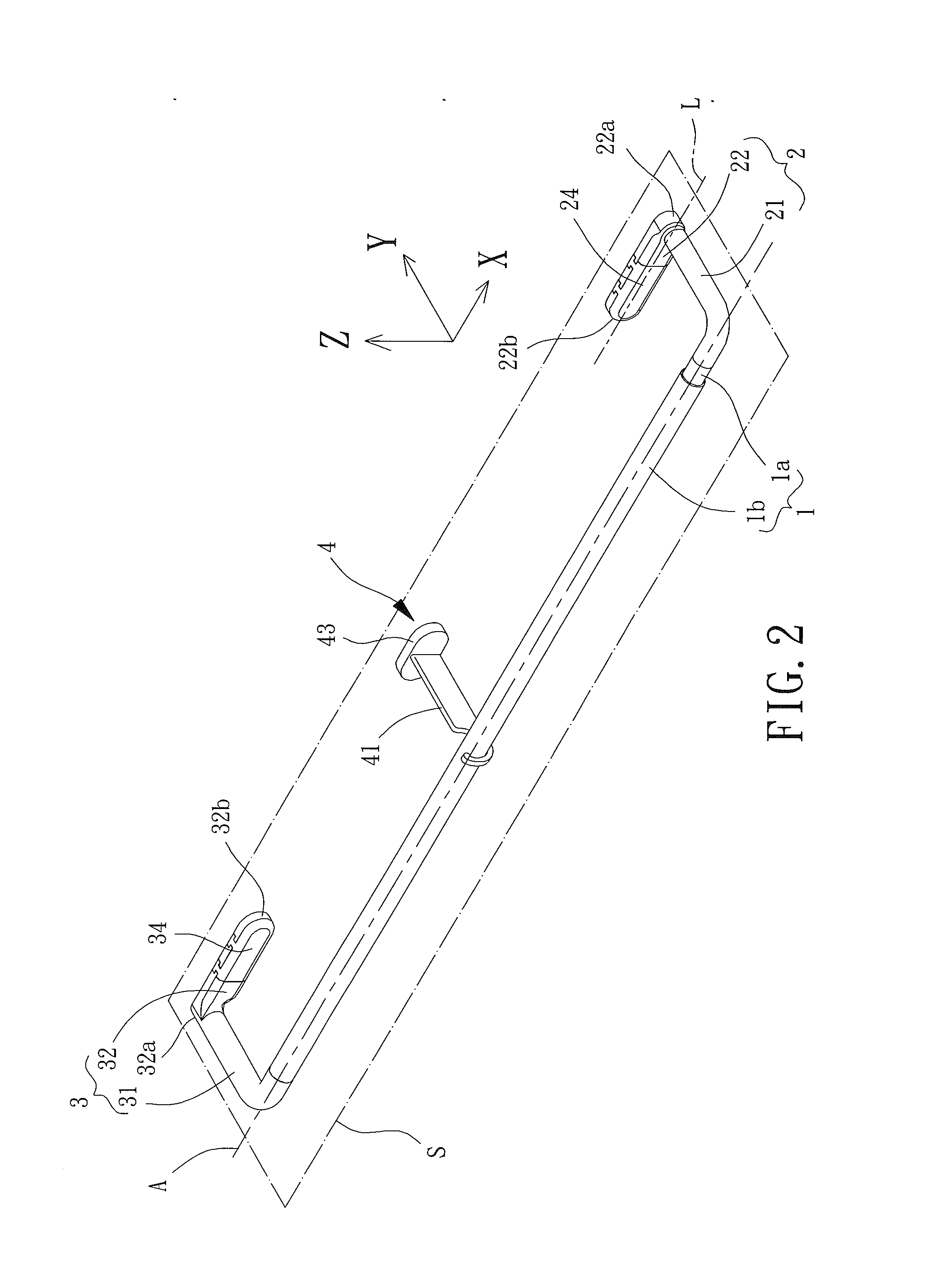
[0029]FIG. 2 shows a curtain fixing device of an embodiment according to the present invention. The curtain fixing device includes a hanging rod 1, a first bracket 2, and a second bracket 3. The first and second brackets 2 and 3 are respectively coupled to two ends of the hanging rod 1.

[0030]With reference to FIGS. 2 and 3, the hanging rod 1 is adapted to be used to hang a curtain. In this embodiment, the hanging rod 1 includes a first tube 1a and a second tube 1b. An end of the first tube 1a is received in an end of the second tube 1b. A user can adjust the overlapped length of the first tube 1a and the second tube 1b and, thus, telescope the hanging rod 1 to permit the hanging rod 1 to be used on windows of different widths. In other embodiments, the hanging rod 1 can include three or more telescopic tubes for use with wider windows, which can be appreciated by a person having ordinary skill in the art. Thus, the hanging rod 1 is not limited to the embodiment shown.

[0031]Each end ...


PUM


Abstract

A curtain fixing device includes a hanging rod and first and second brackets. Each of the first and second brackets includes a spacer section and a fixing section connected to the spacer section. A projection of the spacer section onto the fixing section is located in the fixing section. The spacer section of the first bracket is coupled to a first end of the hanging rod. The spacer section of the second bracket is coupled to a second end of the hanging rod. The fixing sections of the first and second brackets are parallel to the hanging rod.

Description

BACKGROUND OF THE INVENTION[0001]1. Field of the Invention[0002]The present invention relates to a curtain fixing device and, more particularly, to a curtain fixing device that can be fixed to a wall for hanging a curtain.[0003]2. Description of the Related Art[0004]FIG. 1 shows a conventional curtain fixing device 9 including a first rod 91, a second rod 92, a left bracket 93, and a right bracket 94. An end of the first rod 91 receives an end of the second rod 92. The left bracket 93 is fixed to the other end of the first rod 91. The right bracket 94 is fixed to the other end of the second rod 92. The first rod 91 has a longitudinal axis extending in an X direction. The left bracket 93 extends from an end thereof connected to the first rod 91 in the X direction, a Y direction, and a Z direction to the other end of the left bracket 93. A portion of the left bracket 93 extending in the Z direction forms a coupling section 931 by which the left bracket 93 can be fixed to a wall. The r...

Claims


Application Information

Patent Timeline
IPC IPC(8): A47H1/142A47H1/022F16B7/18
CPCA47H1/142A47H1/022F16B7/182F16B9/026A47H2001/0215F16B21/09F16B45/00F16B9/052
Inventor CHENG, LI-MING
Owner CHENG LI MING
Why Eureka
Try Eureka