
Process for determining a time interval

Inactive Publication Date: 2007-04-19
ASM AUTOMATION SENSORIK MESSTECHN GMBH
View PDF4 Cites 5 Cited by
  • Summary
  • Abstract
  • Description
  • Claims
  • Application Information

AI Technical Summary

Benefits of technology

[0015] It is, therefore, an object of the present invention to improve the measuring precision and interference resistance of the time measurement, in particular, with magnetostrictive position sensors in spite of the reduced size of the electronics unit and reduced manufacturing cost.
[0016] Through the conversion into a digital signal and the determination of the time interval to the middle of the digital impulse, the measuring precision is increased and the interference resistance is improved.
[0018] Also, all other features serve to increase the precision and interference resistance of the time measurement, on the one hand, or the reduction of the space requirement for the electronics group and its cost, on the other hand.

Problems solved by technology

A disadvantage of this setup is the low flexibility of the solid state program state machine and the additional effort for communication and division of the processing tasks between the state machine and the microcontroller.
From this results a cost and design disadvantage, since quartzes are expensive in comparison to other resonators and require substantially more space.
A disadvantage of the noise window is the high computation effort for the adaptive positioning of the noise window.
A disadvantage of this set up is not only the effort for the many housing components, but also the reliability of the high number of pin connectors for the internal wiring.
Furthermore, the measurement of the peak amplitude requires an additional effort in the respective circuits.
Alternative embodiments of analog threshold adaptation to avoid step errors significantly increase the hardware effort for comparators, operational amplifiers, hold elements, analog switches and consume more space on the electronics unit.
Also, an additional effort and placement surface on the electronics group are required for implementing the additional comparator.

Method used


Image

  • Process for determining a time interval
  • Process for determining a time interval
  • Process for determining a time interval

Examples


Embodiment Construction

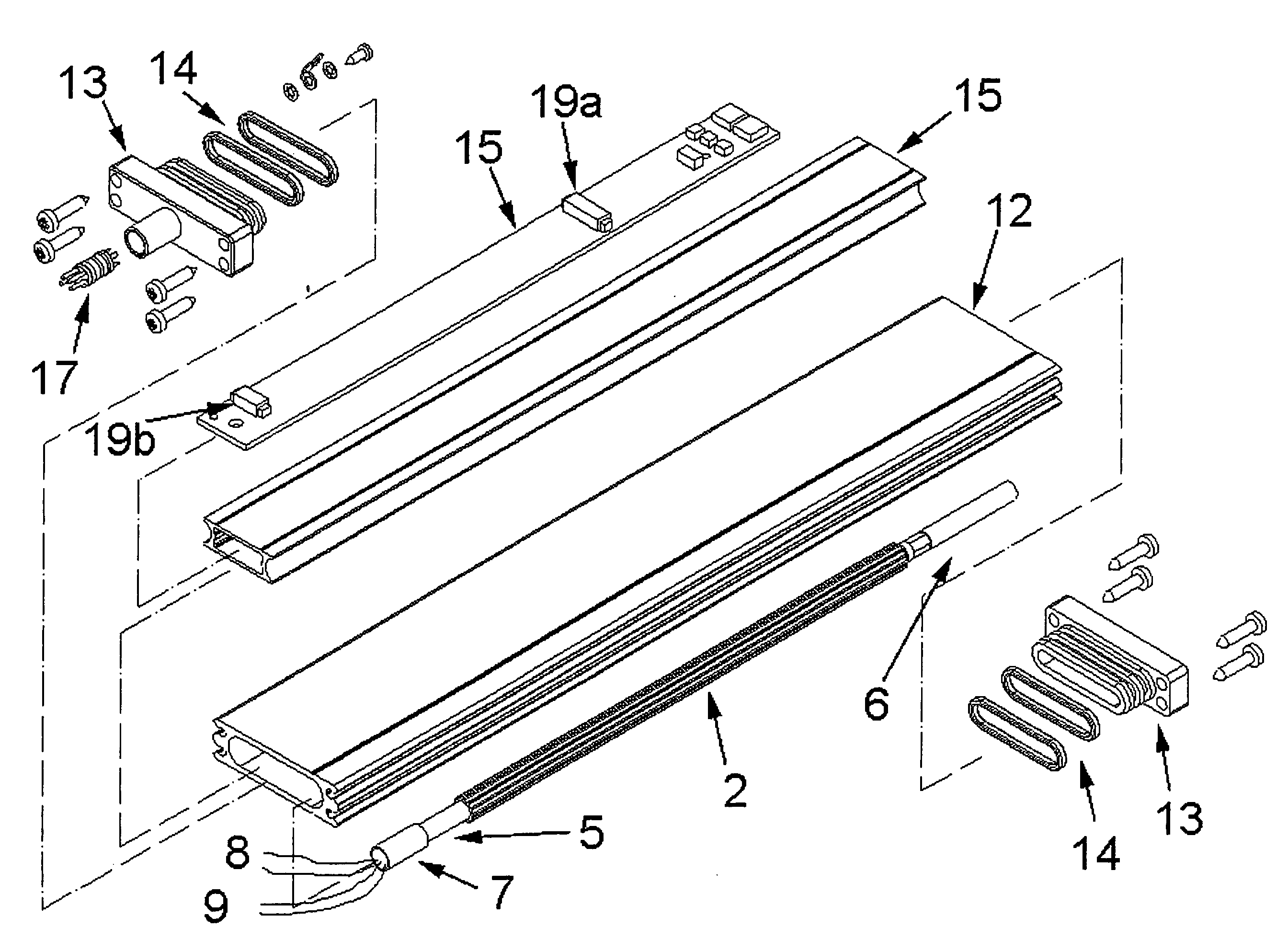
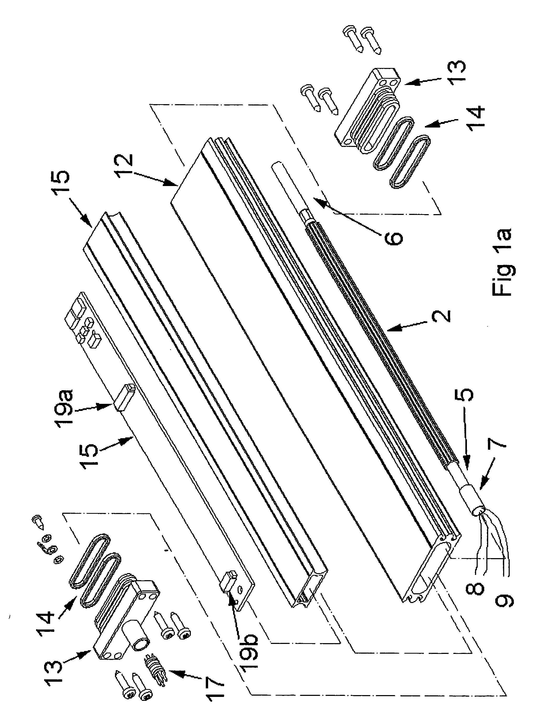
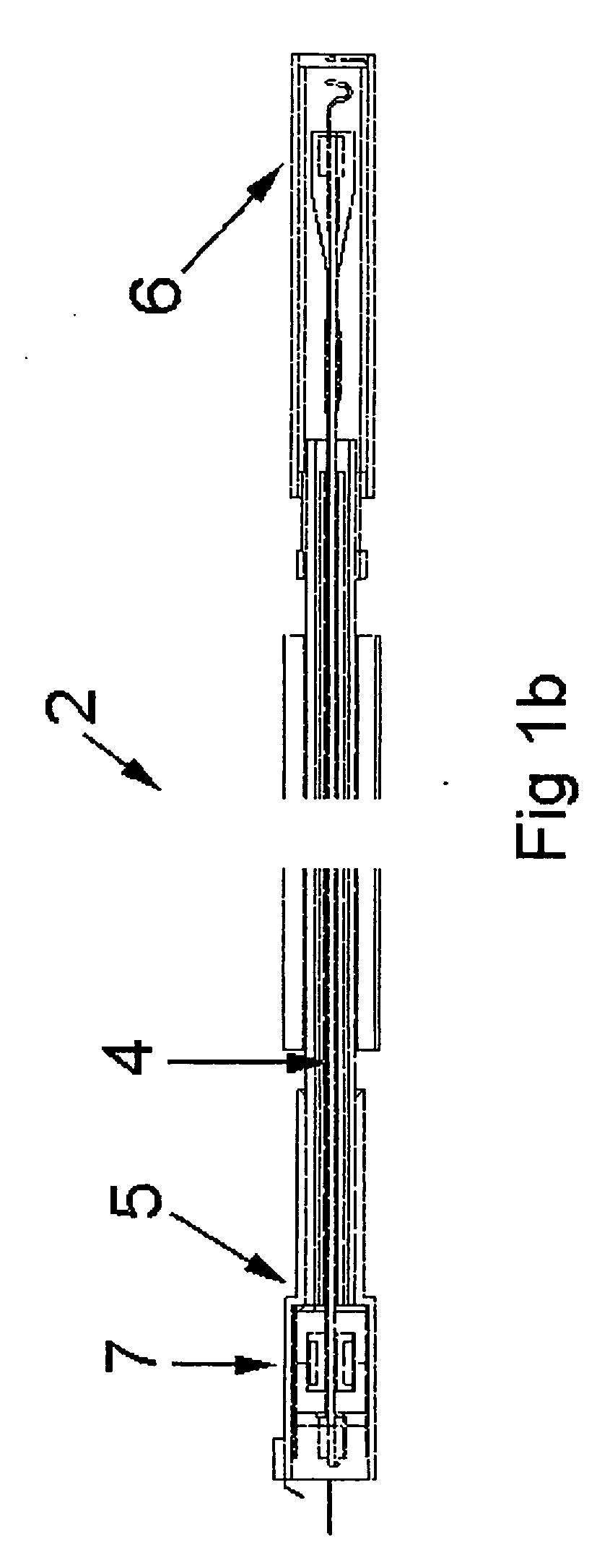
[0032]FIGS. 1a, 1b and FIG. 2 show the layout of a magnetostrictive position sensor according to the invention. The main feature of sensors of this kind is the measurement of the travel duration of a mechanic elastic impulse wave along the wave conductor. In a preferred embodiment, a position magnet (3) is guided along a wave conductor. The wave conductor is integrated into a wave conductor detector unit (2). Via a conductor pair (8) an electrical excitation impulse (11) is supplied to the wave conductor with an impulse duration of approximately two to five microseconds, generating a circular magnetic field along the wave conductor.

[0033] In the position where the magnetic field of the position magnet and the circular magnetic field of the wave conductor overlay, a mechanic elastic impulse wave is generated which propagates along the wave conductor. An impulse detector mounted at the end of the wave conductor detector unit converts the mechanic elastic impulse wave arriving after a...


PUM


Abstract

In order to improve e.g. at a magnetostrictive position sensor the measurement precision and the robustness of the time measurement in spite of low installation size and cost, it is suggested according to the invention to generate a digital position impulse with defined time width from the analog position impulse so, that the middle of the digital impulse is located at the middle of the analog impulse and the time interval can be determined as time differential between the start impulse and the middle of the digital impulse.

Description

CROSS-REFERENCE TO RELATED APPLICATIONS [0001] This application claims priority to German Patent Application Nos. 10 2005 050 170.2 filed 19 Oct. 2005 and 10 2006 041 827.1 filed 6 Sep. 2005. STATEMENT REGARDING FEDERALLY SPONSORED RESEARCH OR DEVELOPMENT [0002] Not Applicable THE NAMES OF THE PARTIES TO A JOINT RESEARCH AGREEMENT [0003] Not Applicable INCORPORATION-BY-REFERENCE OF MATERIAL SUBMITTED ON A COMPACT DISC [0004] Not Applicable BACKGROUND OF THE INVENTION [0005] 1. Field of the Invention [0006] The invention regards a process and a device for determining a time interval, in particular with position sensors, according to the travel time principle, e.g. in magnetostrictive position sensors. [0007] 2. Description of the Related Art [0008] In position sensors according to the travel time principle, a time interval between a starting impulse and a stop impulse is determined whose duration represents the distance of the position indicator, mostly a position magnet, from the me...

Claims


Application Information

Patent Timeline
IPC IPC(8): G01S13/00
CPCG01D5/485
Inventor STEINICH, KLAUS MANFREDWIRTH, PETER
Owner ASM AUTOMATION SENSORIK MESSTECHN GMBH
Learn More