Engine intake control device

Inactive Publication Date: 2005-12-22
MITSUBISHI ELECTRIC CORP
View PDF3 Cites 4 Cited by
  • Summary
  • Abstract
  • Description
  • Claims
  • Application Information

AI Technical Summary

Benefits of technology

[0009] The present invention has been made to solve the problems, and an object of the present invention is to provide an engine intake control device in which components such as attachment brackets and attachment screws for attaching respective solenoid valves

Problems solved by technology

Assembling operations for providing the hose piping for connection to the negative pressure passage, and wiring for electrical connection are laborious.
The cost of components, and the production cost are high.
Since

Method used


Image

  • Engine intake control device
  • Engine intake control device
  • Engine intake control device

Examples


Example

First Embodiment

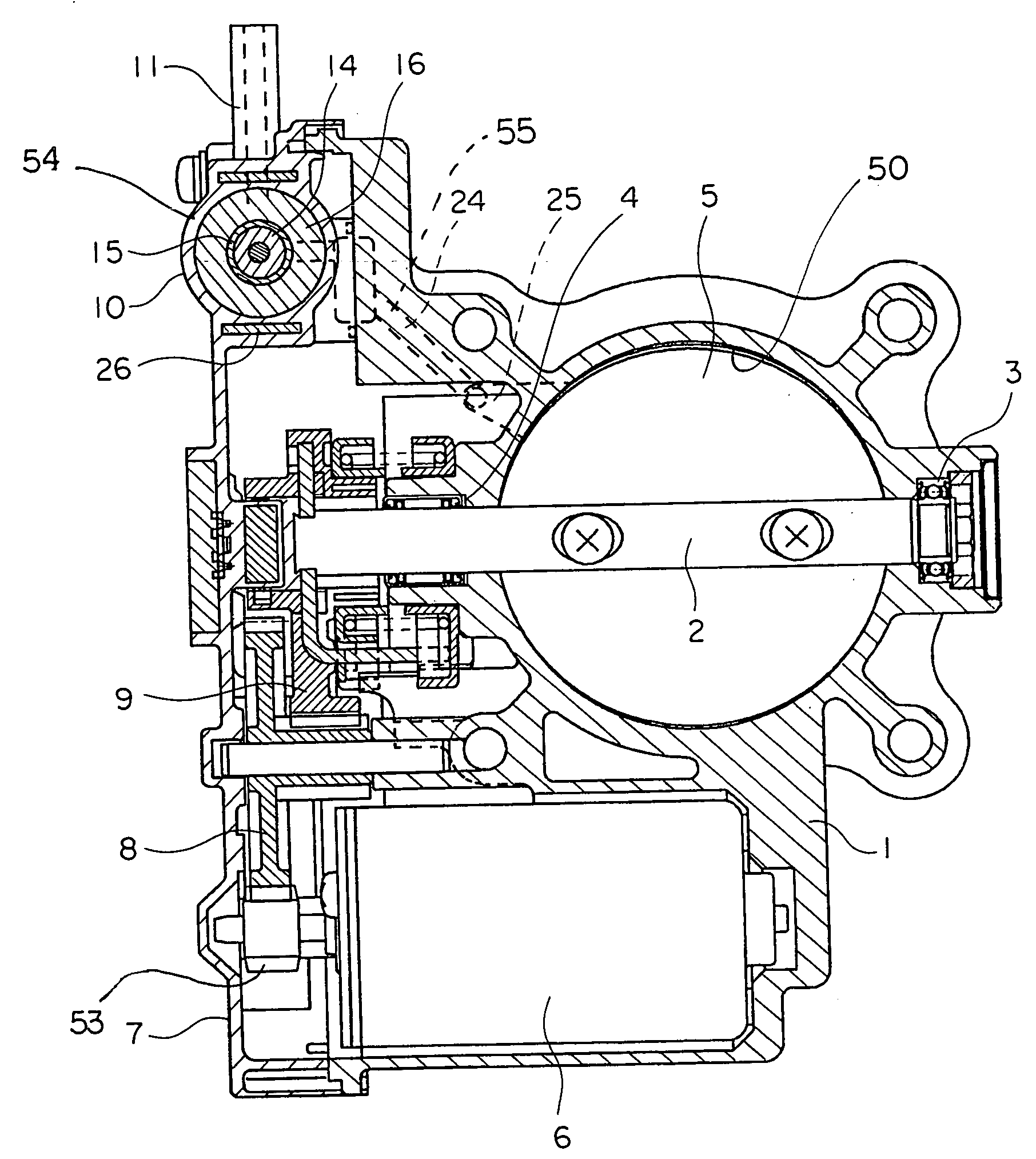
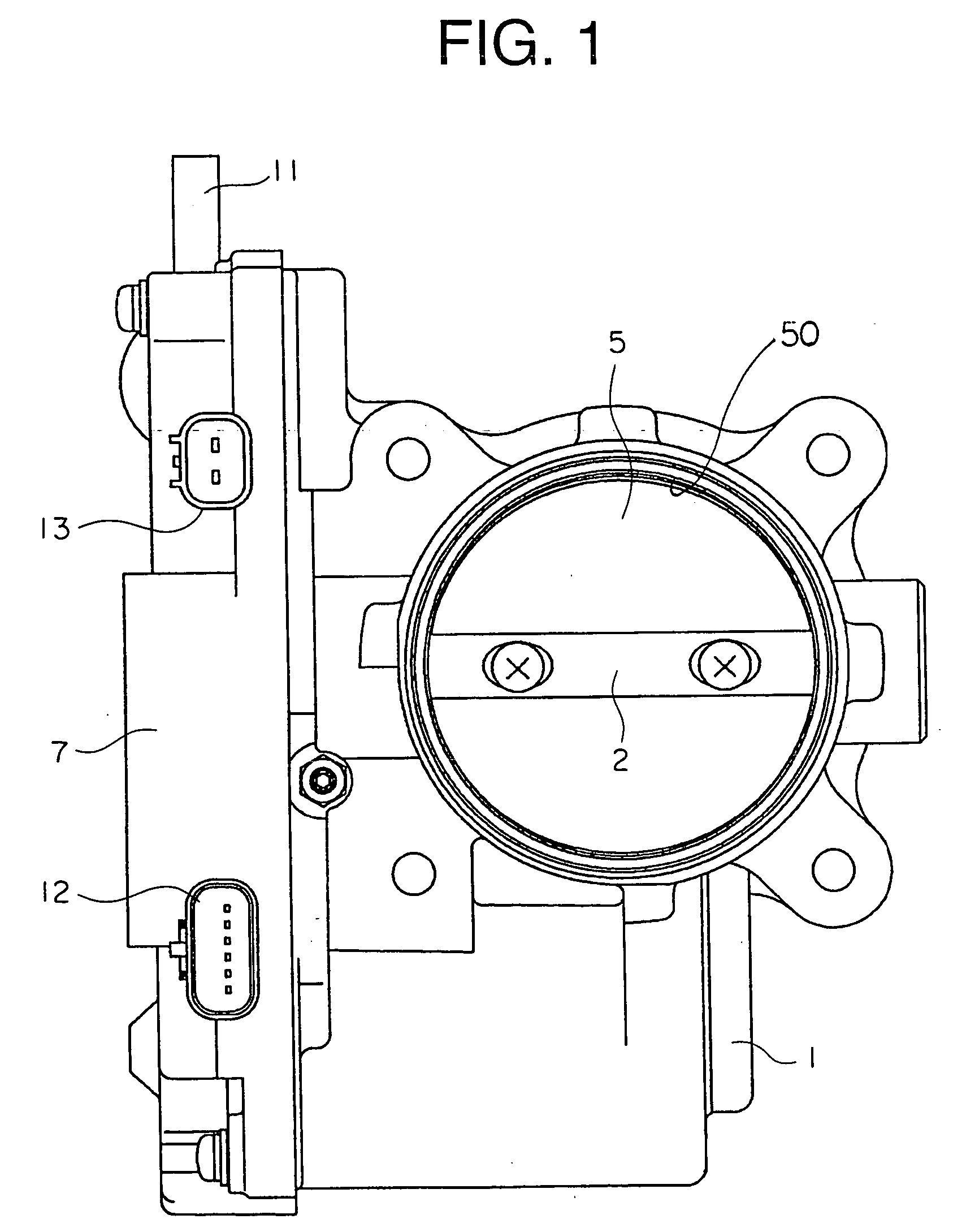
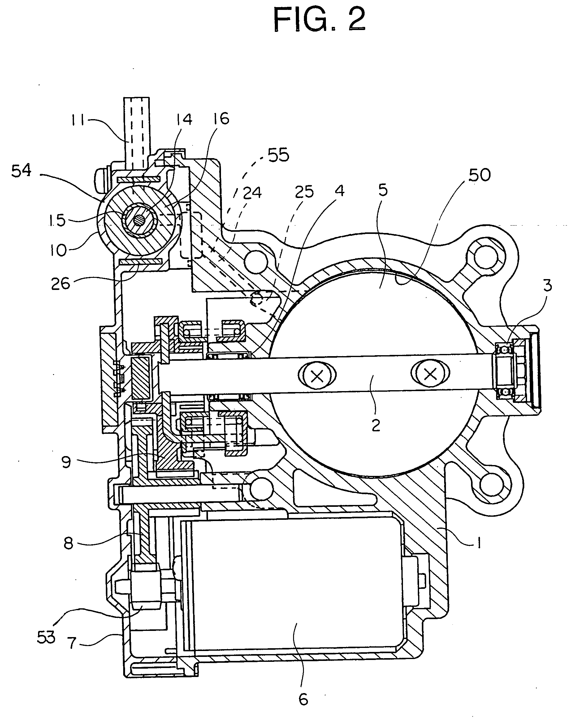
[0021]FIG. 1 is a front view of an engine intake control device according to a first embodiment of the present invention. FIG. 2 is a cross sectional front view of the engine intake control device in FIG. 1. FIG. 3 is a left side view of the engine intake control device in FIG. 1. FIG. 4 is a partial cross sectional right side view of a cover in FIG. 1. FIG. 5 is a rear view of a throttle chamber in FIG. 1, showing an attachment surface to which a surge tank is attached.

[0022] The engine intake control device includes a throttle chamber 1, a throttle valve 5, and an electric motor 6. The throttle chamber 1 forms an air passage 50 in an engine intake system. The throttle valve 5 is provided in the throttle chamber 1 using a valve shaft 2, and is rotatably supported by a first bearing 3 and a second bearing 4. The electric motor 6 is provided outside the air passage 50.

[0023] Further, the engine intake control device includes a coupling mechanism 51, a cover 7, and ...

Example

Second Embodiment

[0039]FIG. 6 is a front view showing an engine intake control device according to a second embodiment of the present invention.

[0040] In the first embodiment, the electrical connector 13 of the solenoid valve 10, and the electrical connector 12 of the electric motor 6 and the rotational angle sensor for detecting throttle opening degree are separately provided. In contrast, in the second embodiment, these connectors 12 and 13 are integrated into a single connector 30, and the connector 30 is provided integrally with the cover 7.

[0041] Other structural features of the second embodiment are the same as those of the first embodiment.

[0042] In the engine intake control device, the number of assembling operations is reduced in comparison with the case in which the connectors 12 and 13 are provided separately on the cover 7.

[0043] Alternatively, the electrical connector of the solenoid valve 10 and the electrical connector of only one of the electric motor and the ro...

Example

Third Embodiment

[0044]FIG. 7 is a cross sectional front view showing an engine intake control device according to a third embodiment of the present invention. In the third embodiment, a drive circuit 40 for driving the solenoid valve 10 is attached to the cover 7.

[0045] Other structural features of the third embodiment are the same as those of the first embodiment.

[0046] In the engine intake control device, it is possible to reduce the raise of temperature in the engine control unit, the reliability is good, and the size is small in comparison with the case in which the engine control unit has a drive circuit for driving the solenoid valve.

[0047] In the embodiments as described above, the actuator of the variable intake device is used as the diaphragm type negative pressure actuator. The variable intake device applies the negative pressure in the surge tank to the diaphragm type negative pressure actuator and interrupts application of the negative pressure to the diaphragm type ...


PUM


Abstract

Provide is an engine intake control device in which components such as attachment brackets, attachment screws for attaching respective solenoid valves around an engine are not required, and the number of attachment operations is reduced. The engine intake control device includes: a throttle chamber (1); a throttle valve (5) rotatably provided in the throttle chamber (1) using a valve shaft (2); an electric motor (6) provided outside an air passage (50); a coupling mechanism (51) for transmitting a driving force of the electric motor (6) to the valve shaft (2); a cover (7) provided on one side of the throttle chamber (1) to cover the coupling mechanism (51); and a solenoid valve (10) attached to the throttle chamber (1) for applying a negative pressure in a surge tank to an external negative pressure actuator and interrupting application of the negative pressure to the external negative pressure actuator. The solenoid valve (10) is provided integrally with the cover (7).

Description

BACKGROUND OF THE INVENTION [0001] 1. Field of the Invention [0002] The present invention relates to an engine intake control device for adjusting air intake volume of an engine by driving an electric motor to open and close a throttle valve. [0003] 2. Description of the Related Art [0004] An engine intake control device in which an electric motor is used to open and close a throttle valve for adjusting air intake volume of an engine has been put into practice. [0005] Further, in recent years, a variable intake device that switches intake passages by utilizing intake pulsation and intake inertia to increase air intake volume over a wide range of engine revolutions for improving engine performance, and an air flow control valve device which controls an air flow introduced into a cylinder of an engine in accordance with operating conditions, and generates a swirl flow or a tumble flow to improve mixing condition of the fuel and air and combustion condition for improving engine perform...

Claims


Application Information

Patent Timeline
IPC IPC(8): F02D11/10
CPCF02D11/10
Inventor SUZUKI, MIKIHIKO
Owner MITSUBISHI ELECTRIC CORP
Why Eureka
Try Eureka