
Ink Containment System and Ink Level Sensing System for an Inkjet Cartridge

a technology inkjet cartridge, which is applied in the direction of spring/damper, ring spring, shock absorber, etc., can solve the problems of increasing the complexity, cost and repair of the cartridge, and the inability to meet the needs of ink level sensing system,

Active Publication Date: 2009-11-26
VIDEOJET TECH INC
View PDF56 Cites 30 Cited by
  • Summary
  • Abstract
  • Description
  • Claims
  • Application Information

AI Technical Summary

Benefits of technology

The invention is an ink containment system for an inkjet cartridge that stores ink for printing. The system includes a housing with multiple walls, a rigid basin member, and a rigid moveable plate. A flexible membrane is attached to both the basin member and the plate, creating an ink reservoir. A spring-biased mechanism is positioned between the basin member and plate, creating negative pressure within the ink reservoir while the basin member remains stationary. The system also includes an ink level sensing system that detects when the ink level reaches a predetermined level and a controller that counts the ink drops ejected during printing to determine the remaining ink level. The technical effects of this invention include improved ink containment and ink level sensing for efficient ink usage and prevention of ink cartridge emptying.

Problems solved by technology

A drawback in this design is that the plates, especially metal plates, the flexible membrane may have a tendency to tear at the points or lines of engagement of the membrane against edges of the plate.
As noted above, the flexible membrane is preformed having a centrally located area on the membrane for receiving the plate, which may create additional steps and costs in the manufacture of the cartridge.
However, such valves and pumping mechanism increase the complexity, cost and repair of the cartridges.
If the volume of ink drops below the minimum level the cartridge risks blank ejections, which may damage the printhead.

Method used


Image

  • Ink Containment System and Ink Level Sensing System for an Inkjet Cartridge
  • Ink Containment System and Ink Level Sensing System for an Inkjet Cartridge
  • Ink Containment System and Ink Level Sensing System for an Inkjet Cartridge

Examples


Embodiment Construction

[0069]Reference will now be made in detail to the embodiments consistent with the invention, examples of which are illustrated in the accompanying drawings. Wherever possible, the same reference numerals are used throughout the drawings and refer to the same or like parts.

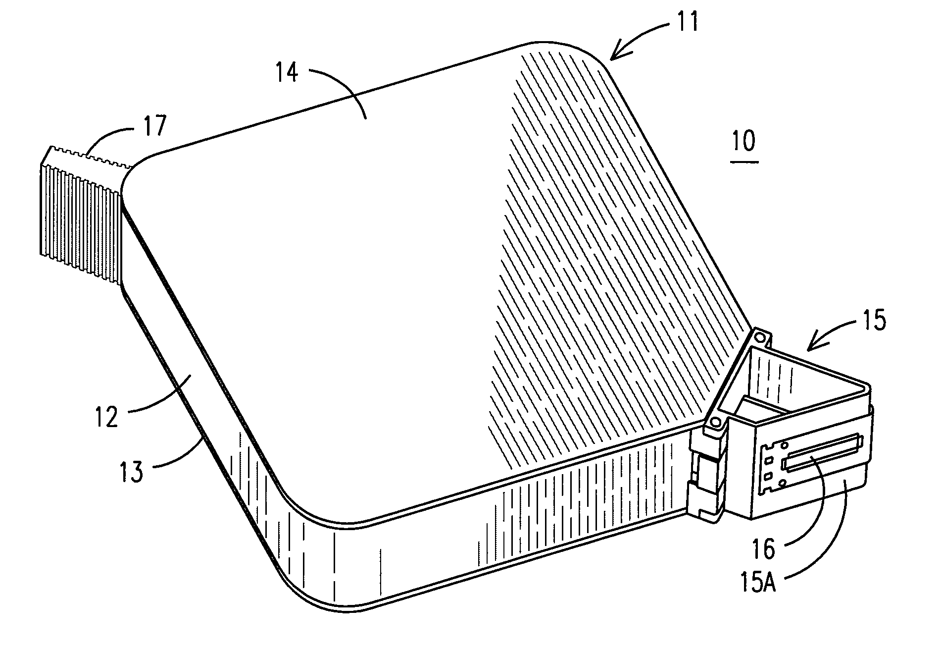
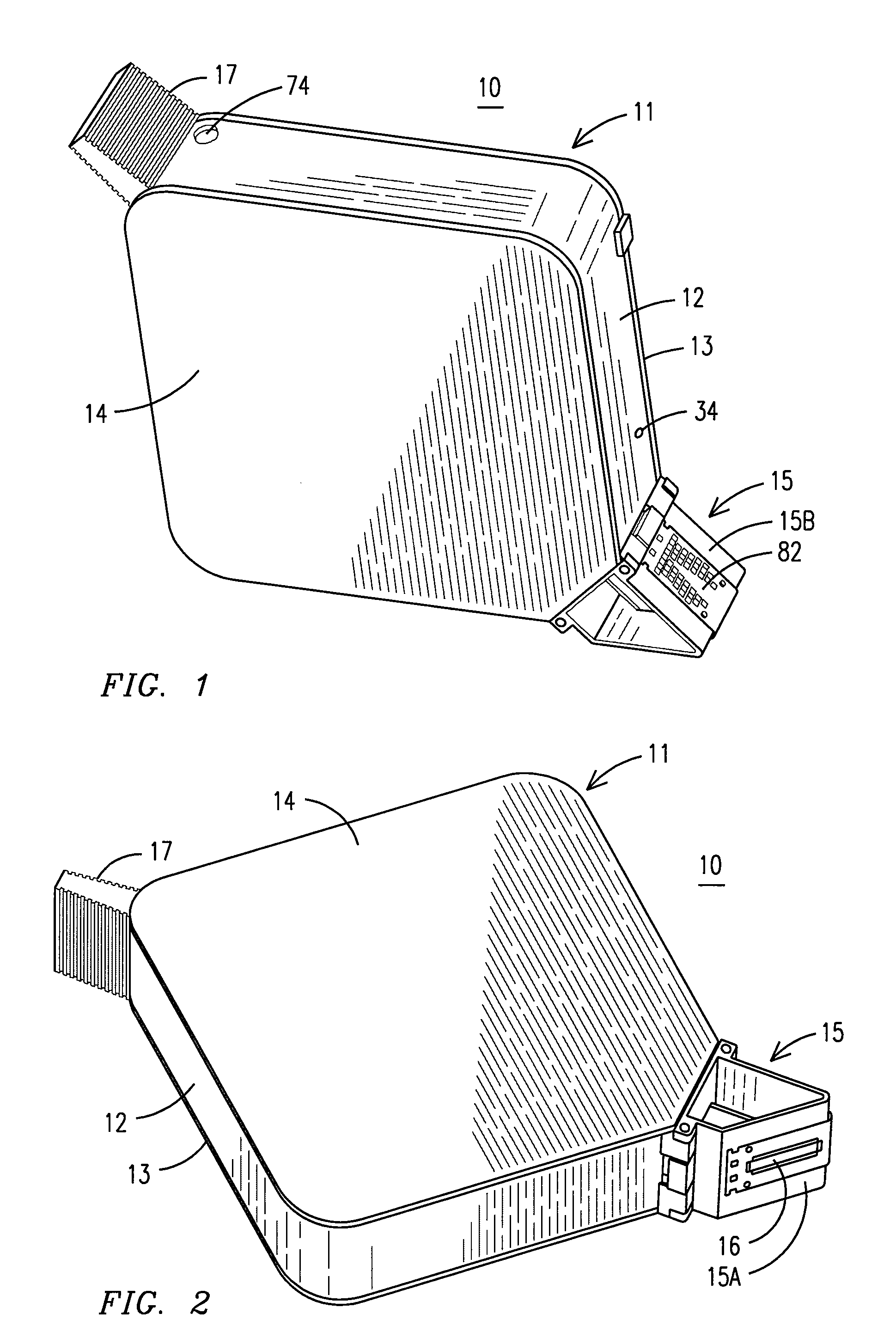
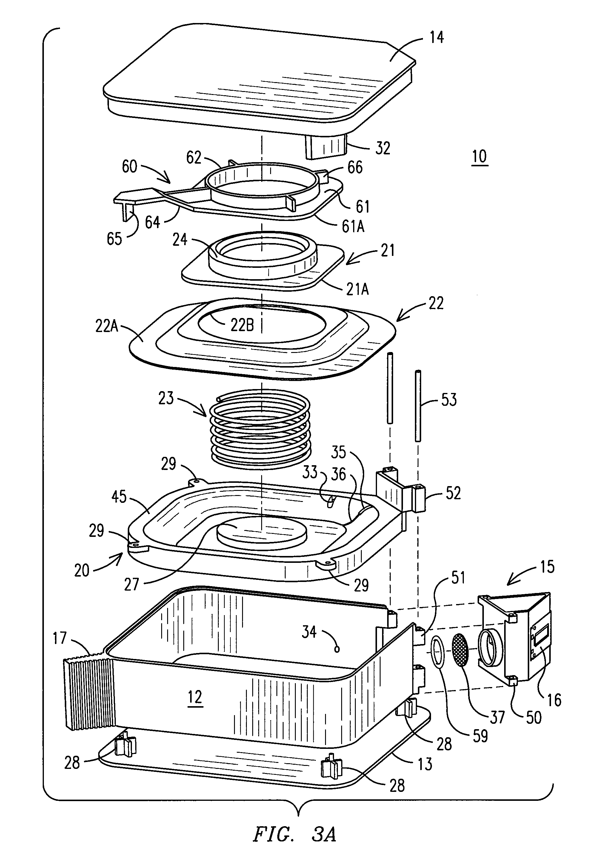
[0070]An inkjet cartridge 10 shown in FIGS. 1 and 2 may be mounted on a moveable or stationary carrier for printing and has a printhead 16 in fluid communication with an ink reservoir 19 encased within housing 11. Responsive to printing commands from a controller (not shown), the printhead 16 discharges ink from the ink reservoir 19 onto a print medium (not shown). The housing 11 comprises a sidewall 12, a first cover plate 13 and a second cover plate 14. For purposes of assembling the cartridge 10, either the first cover plate 13 or second cover plate 14 may be integrally formed with the sidewall 12. The other cover plate 13 or 14 is then affixed to the sidewall 12 encasing an ink reservoir 19 within housing 11. A...


PUM


Abstract

An ink containment system for an inkjet cartridge, for storing ink for printing, comprises a housing having a plurality of walls. A rigid basin member and a rigid moveable plate are disposed within the housing. A flexible membrane is affixed to a surface of the basin member and to a surface of the plate forming an ink reservoir within the basin member, plate and flexible membrane. A spring-biased mechanism is disposed between the basin member and plate, for biasing the plate apart from the basin member, generating a negative pressure within the ink reservoir and the basin member remaining stationary relative to the movement of the plate.

Description

FIELD OF THE INVENTION[0001]An embodiment of the invention pertains to inkjet printers and inkjet cartridges. More specifically, an embodiment of the invention relates to ink containment systems or ink reservoirs used to store ink in an inkjet cartridge.BACKGROUND OF THE INVENTION[0002]Typically, an inkjet cartridge comprises an outer housing within which an ink containment system or ink reservoir is disposed in fluid communication with an inkjet printhead. A mechanism linked to the ink reservoir generates a negative pressure or backpressure that is maintained within a sufficient range to prevent ink from leaking from the printhead, but also allow injection of ink for printing.[0003]Controlling the internal pressure within the ink reservoir has been the subject patents for more that twenty years. Earlier now expired patents including U.S. Pat. No. 4,422,084 (the '084 Patent); U.S. Pat Nos. 4,509,062; and, 4,500,895 (the '895 Patent) disclose a variety of mechanisms used to generate ...

Claims


Application Information

Patent Timeline
Patent Type & Authority Applications(United States)
IPC IPC(8): B41J29/38B41J2/175
CPCB41J2/17513B41J2/1753B41J2002/17516B41J2/17556B41J2/17596B41J2/17553
Inventor GILSON, CHARLES W.KIMERLING, THOMAS E.THACKRAY, MARK R.TRUEBA, KENNETH E.BENIGNI, SCOTT T.FOLKERS, JOHN P.
Owner VIDEOJET TECH INC
Learn More