Angled LED Light Module

a technology of led light modules and led light tubes, which is applied in the direction of semiconductor devices, lighting and heating apparatus, and light source support devices. it can solve the problems of incandescent lights that typically have shortened life-spans and incandescent lights that are typically less energy-efficient than light modules

Inactive Publication Date: 2009-11-26
LODHIE PERVAIZ
View PDF20 Cites 16 Cited by
  • Summary
  • Abstract
  • Description
  • Claims
  • Application Information

AI Technical Summary

Problems solved by technology

Additionally, incandescent lights typically have shortened life-spans than light modules using LED

Method used


Image

  • Angled LED Light Module
  • Angled LED Light Module
  • Angled LED Light Module

Examples


Embodiment Construction

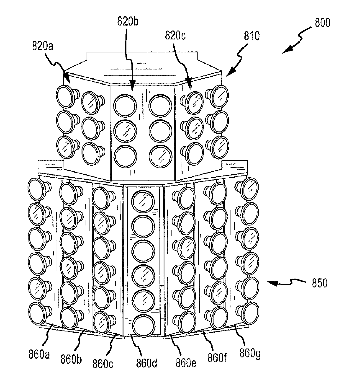
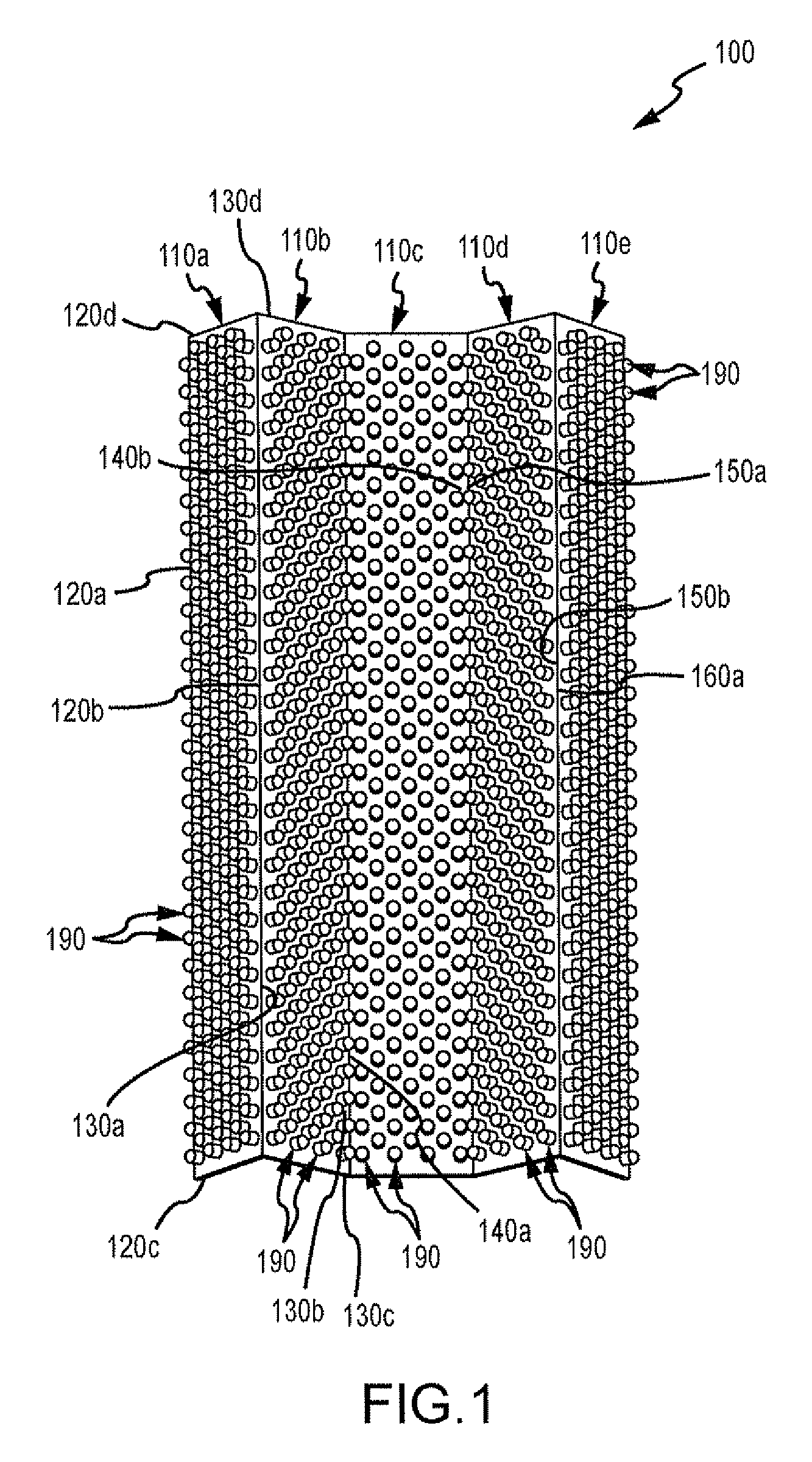
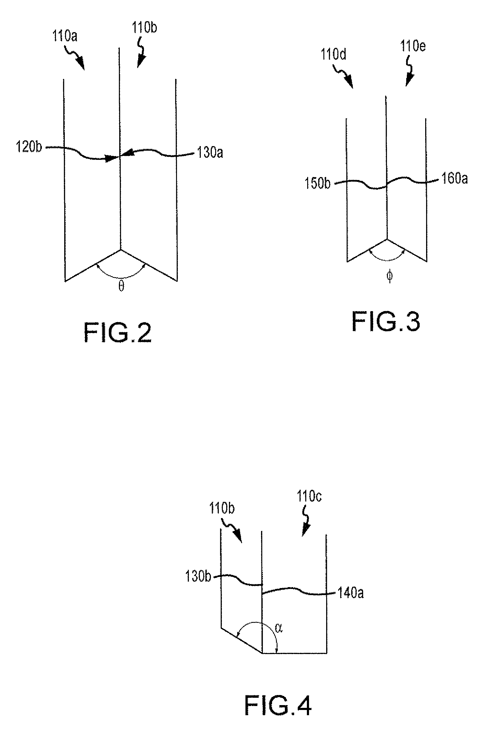
[0030]The detailed description set forth below in connection with the appended drawings is intended as a description of various embodiments of the present invention and is not intended to represent the only embodiments in which the present invention may be practiced. Each embodiment described in this disclosure is provided merely as an example or illustration of the present invention, and should not necessarily be construed as preferred or advantageous over other embodiments. The detailed description includes specific details for the purpose of providing a thorough understanding of the present invention. However, it will be apparent to those skilled in the art that the present invention may be practiced without these specific details. In some instances, well-known structures and devices are shown in block diagram form in order to avoid obscuring the concepts of the present invention. Acronyms and other descriptive terminology may be used merely for convenience and clarity and are no...


PUM


Abstract

An angled LED light module comprising at least two boards arranged at an angle relative to each other; and a plurality of LED bulbs mounted on the at least two boards, wherein the at least two boards and the plurality of LED bulbs form a single light source. In one aspect, the at least two boards are printed circuit boards. In one aspect, the angled LED light module comprises two stages.

Description

CLAIM OF PRIORITY UNDER 35 U.S.C. §119[0001]The present Application for Patent claims priority to Provisional Application No. 61 / 055,835 entitled Angled LED Light Module filed May 23, 2008, and assigned to the assignee hereof and hereby expressly incorporated by reference herein.FIELD[0002]This disclosure relates generally to lighting sources. More particularly, the disclosure relates to a Light-Emitting Diode (“LED”) lighting source.BACKGROUND[0003]LED bulbs are light sources that use semiconductor materials rather than filaments to emit light. LED bulbs are generally more efficient light sources than incandescent light bulbs because LED bulbs are nearly monochromatic and emit light within a very narrow range of wavelengths. LED bulbs also generally last many times longer than incandescent light bulbs.[0004]Street light posts can be fitted with light sources to illuminate a street, parking lot, walkway, a building, etc. Historically, incandescent lights with filament type bulbs hav...

Claims


Application Information

Patent Timeline
IPC IPC(8): F21V21/00
CPCF21K9/00F21W2131/103H05K2201/10106H05K1/14H05K2201/046F21Y2101/02F21Y2115/10
Inventor LODHIE, PERVAIZ
Owner LODHIE PERVAIZ
Why Eureka
Try Eureka