Inflatable pneumatic bag and the manufacture method thereof

a pneumatic bag and air-flow technology, applied in the field of inflatable bags, can solve the problems of air-flow in the rest of the air-flow tubes, and achieve the effects of saving effective filling time, avoiding damage, and effective time-saving

Active Publication Date: 2009-12-03
LIAO CHIEH HUA
View PDF13 Cites 12 Cited by
  • Summary
  • Abstract
  • Description
  • Claims
  • Application Information

AI Technical Summary

Benefits of technology

[0010]Another objective of the invention is to provide an inflatable pneumatic bag that may effectively overcome reverse air flow and further prevent air escape.
[0011]Another objective of the invention is to provide an inflatable pneumatic bag that may fill all the air tubes at one time and therefore save the filling time effectively.
[0012]To achieve the above objectives, in one aspect, the invention provides an inflatable pneumatic bag with two inner layers and a wall-attached air passage configuration. Two outer layers are provided, one overlying the other. Two inner layers are between the two outer layers. On one plane of the inner layers not facing the outer layers is coated with multiple heat-resistant materials on the regions along the plane. The regions are arranged in a row and separate from each other. During a heat sealing operation, the heat seal lines of the outer layers are sealed to form a pneumatic passage, multiple air ingress holes, and multiple air tubes. The air ingress holes are between the pneumatic passage and the air tubes, which provide a connection allowing air flow between them. The two inner layers are connected to the outer layers with two traverse seals which are formed by heat sealing operation. And the air ingress holes are formed in the regions of the plane of the inner layer covering with heat-resistant materials which may prevent miscibility during the heat sealing operation.
[0016]In one embodiment, an inflatable pneumatic bag includes a pneumatic hole for transferring air along a pneumatic passage. The inflatable pneumatic bag provides multiple air ingress holes and air passages for a single air tube. Air, which is applied to the pneumatic hole, moves along the pneumatic passage and then through the air ingress holes and the air passages to fill all the air tubes. The pneumatic hole may be disposed at either end of the pneumatic passage. When the air tube is filled with air, the inner layers, pressed by air within the air tube cover, and then close the air ingress holes. Therefore the reverse air flow is overcome. The curve-shaped air passage narrows as the pressure in the air tube increase so that the air tube's air escape is prevented. Since each air tube provides more than one air ingress holes and air passages, the filling of all the air tubes becomes substantially efficient and effectively time-saving.
[0017]Among the advantages of the invention are the following. The invention provides a pneumatic hole at either end of the pneumatic passage to continuously fill all the air tubes. Either of inner layer settings (single or two inner layers) may overcome reverse air flow, as well as the air passage (wall-attached or suspension type) further prevents air escape. Each of the air tubes is separate. Even under certain circumstance, one or more of the air tubes might leak, the remainder still functions. The air chamber and multiple pneumatic passages arrangement that enables air distributing to all multiple pneumatic passages at one time saves the filling time effectively. By providing more air ingress holes and air passages to a single air tube; filling air into the air tube becomes substantially efficient. The inflatable pneumatic bag of the invention may use to wrap variety of products in an attempt to avoid damages that inevitably occur during the shipment or other circumstances.

Problems solved by technology

However, when one of the air tubes leaks, the rest of the air tubes also run out of air since all the air tubes are connected through a shared passage.

Method used


Image

  • Inflatable pneumatic bag and the manufacture method thereof
  • Inflatable pneumatic bag and the manufacture method thereof
  • Inflatable pneumatic bag and the manufacture method thereof

Examples


Embodiment Construction

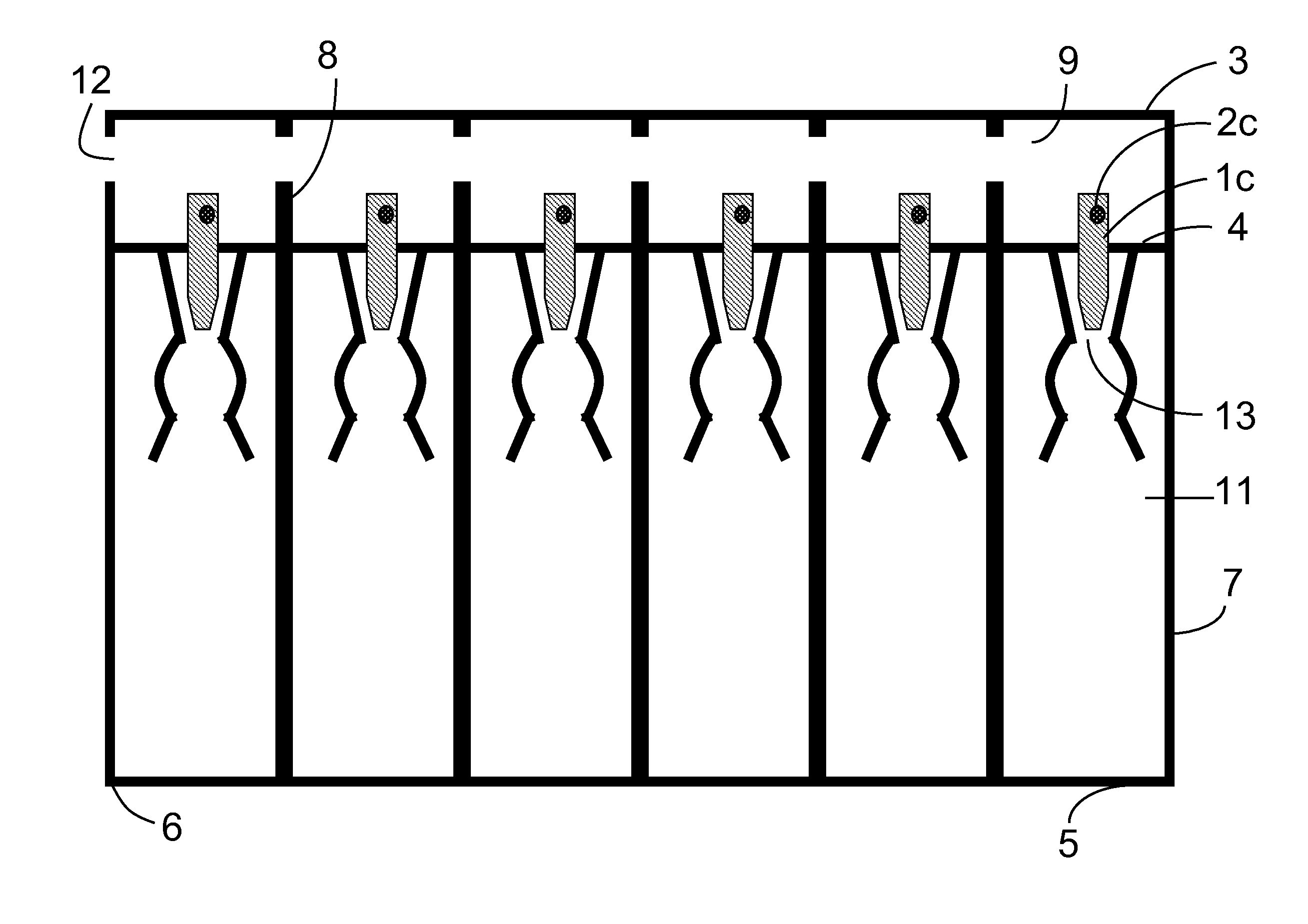
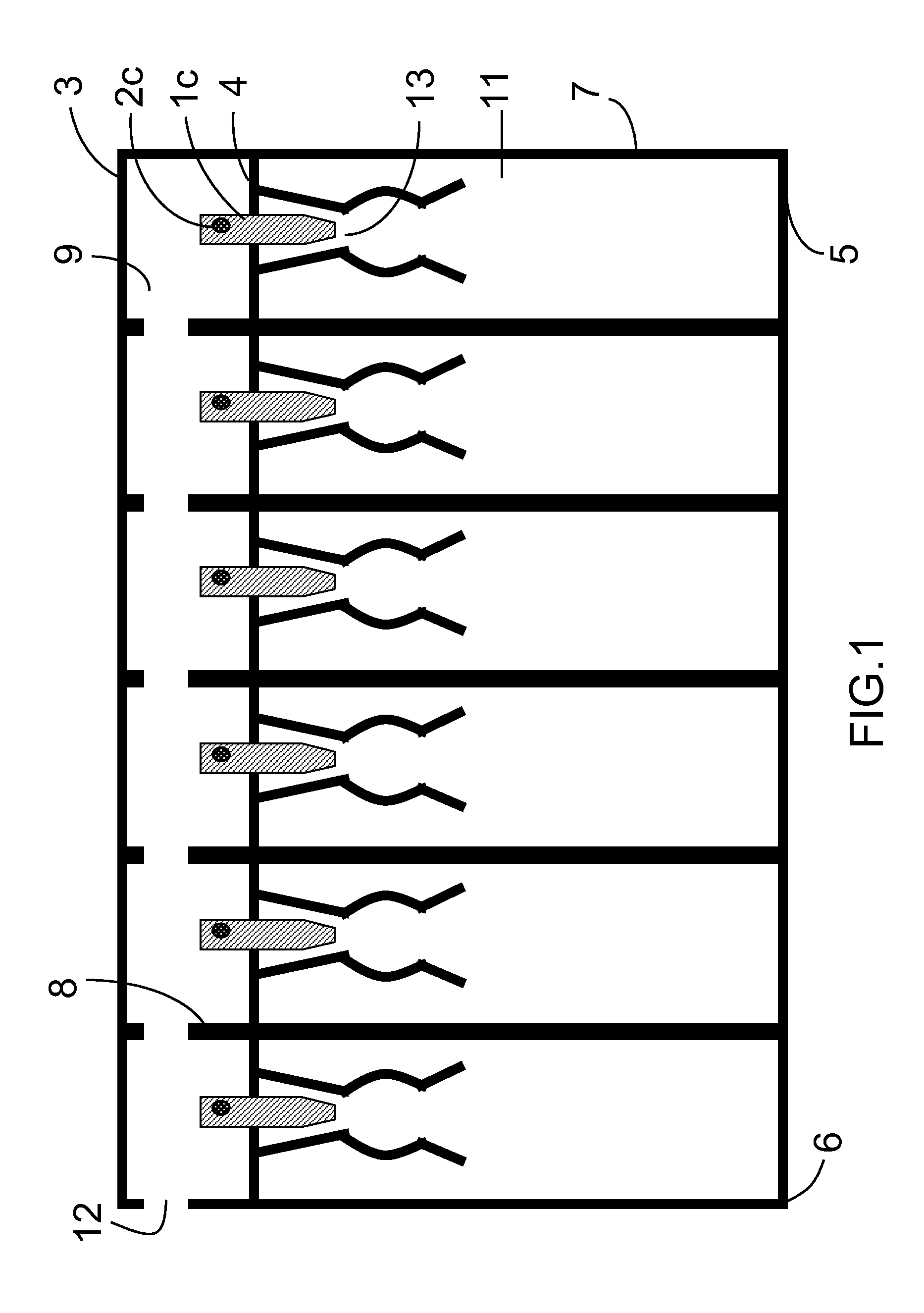
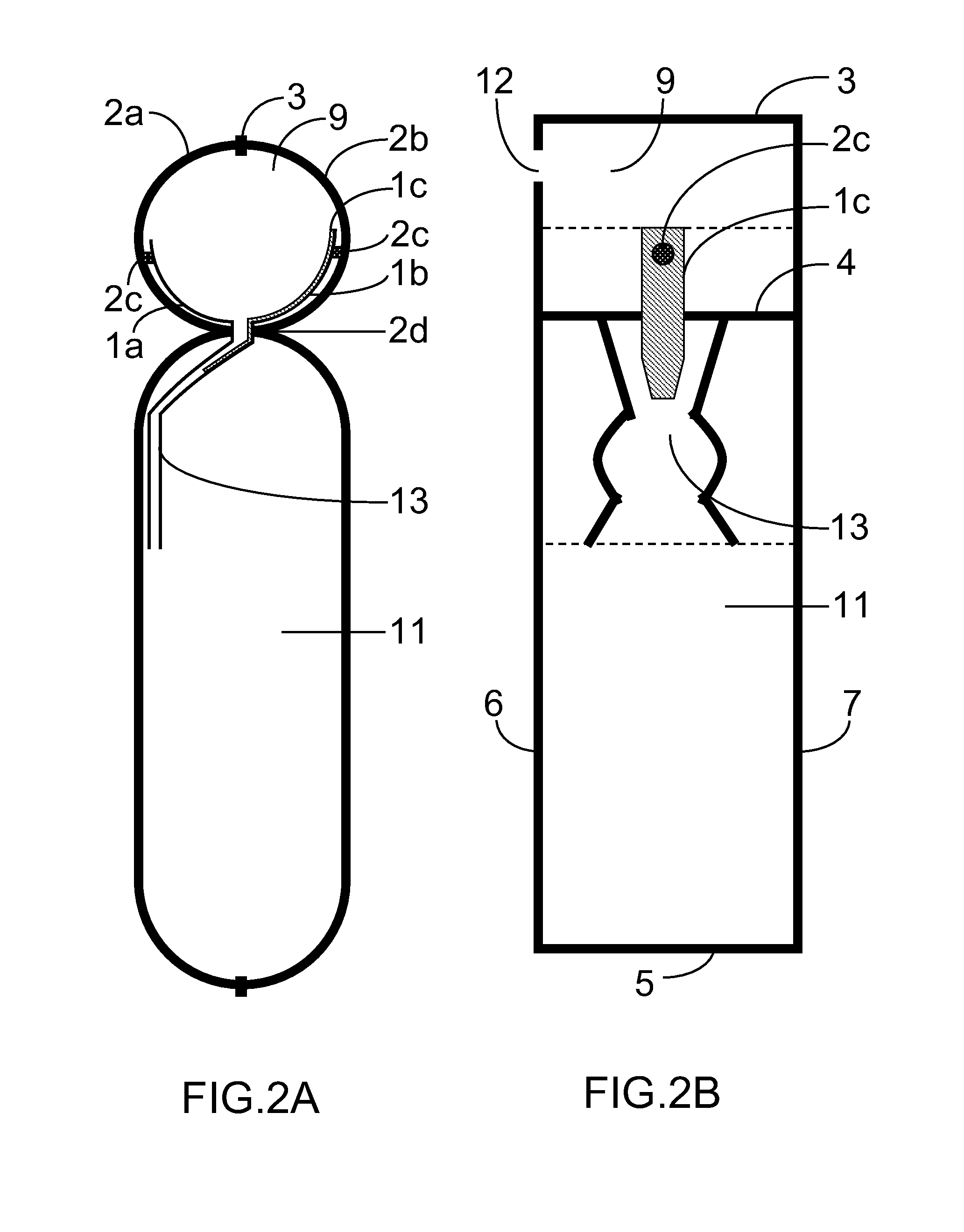
[0027]Referring to FIG. 1, 2A, 2B, an inflatable pneumatic bag with two inner layers and a wall-attached air passage configuration is described. Two outer layers 2a, 2b are provided, one overlying the other. Two inner layers 1a, 1b are between the two outer layers 2a, 2b. On one plane of the inner layers 1a, 1b not facing the outer layers 2a, 2b is coated with multiple heat-resistant materials 1c on the regions along the plane. The regions are arranged in a row and separate from each other. During a heat sealing operation, the heat seal lines 3, 4, 5, 6, and 7 of the outer layers 2a, 2b are sealed to form a pneumatic passage 9, multiple air ingress holes 2d, and multiple air tubes 11. The air ingress holes 2d are between the pneumatic passage 9 and the air tubes 11, which provide a connection allowing air flow between them. At least one projection portion 8 is positioned in the pneumatic passage 9, as shown in FIG. 1, to connect the two outer layers 2a and 2b to the inner layers 1a ...


PUM


Abstract

An inflatable pneumatic bag is disclosed. An inflatable pneumatic bag includes a pneumatic hole disposed at one end of a pneumatic channel. Air, which is applied to the pneumatic hole, moves along the pneumatic channel, then through air ingress holes covered with inner layers which are removed by the expansion of the outer layers to fill all the air tubes. When the air tube is filled with air, one or more inner layers cover and then close the air ingress hole to overcome reverse air flow. Then, a curve-shaped air passage in the air tube narrows to further prevent air escape. With the inner layer, effectively overcoming reverse air flow, and the air passage, further preventing air escape, the inflatable pneumatic bag filled with air may last for a substantial long period of time.

Description

CROSS-REFERENCES TO RELATED APPLICATION[0001]The present application is a continuation application of U.S. patent application Ser. No. 11 / 430,949, filed on May 10, 2006, which is hereby incorporated by reference.BACKGROUND OF THE INVENTION[0002]1. Field of Invention[0003]The present invention relates to an inflatable bag, more particularly to an inflatable pneumatic bag that may continuously fill all the air tubes at one time and effectively prevent air escape.[0004]2. Description of Related Art[0005]Conventional inflatable bags are heat-sealed to form one or more air tubes which include air ingress holes to fill the air tubes for the use as buffering wrapping material.[0006]U.S. patent application (Publication No. 2005 / 0109411 A1) discloses a plurality of separate, independent air tubes. Each of the air tubes includes an air ingress hole for filling air. The air tube includes two inner layers connecting to the outer layers. When the air tube is filled with air, the two inner layers...

Claims


Application Information

Patent Timeline
Patent Type & Authority Applications(United States)
IPC IPC(8): B65D30/22B65D30/24B31B49/04B31B70/00
CPCB65D81/052
Inventor LIAO, CHIAN HUAJIAN, BO XIN
Owner LIAO CHIEH HUA
Why Eureka
Try Eureka