Transfacet fixation assembly and related surgical methods

a transfacet and fixing device technology, applied in the field of minimally invasive, surgically implantable spinal devices and systems, can solve the problems of not all spinal morphologies supporting the utilization of such transfacet bolts or clamping mechanisms, and no substantially v-shaped transfacet bolt assembly is currently available or in existen

Inactive Publication Date: 2009-12-17
CTL MEDICAL CORP
View PDF11 Cites 88 Cited by
  • Summary
  • Abstract
  • Description
  • Claims
  • Application Information

AI Technical Summary

Benefits of technology

[0005]In one exemplary embodiment, the present invention provides a transfacet fixation assembly, including: an engaging bolt; and a receiving bolt selectively coupled to and engaged with the engaging bolt at an angle of between about 30 degrees and about 120 degrees; wherein each of the engaging bolt and the receiving bolt is configured to be disposed through a hole or bore formed through one of a plurality of bony structures making up a portion of a facet joint of a spine. Optionally, the engaging bolt includes a spherical distal end for engaging a locking sleeve disposed at a distal end of the receiving bolt. Optionally, the locking sleeve includes a slot mechanism that locks the engaging bolt to the receiving bolt. Preferably, each of the engaging bolt and the receiving bolt is configured to selectively receive a washer. Optionally, each of the washers includes a superior surface including a radial, ratcheting antirotation surface disposed concentrically about a central hole or bore of the washer. Optionally, each of the washers includes an inferior surface including a radial antirotation friction structure disposed concentrically about a central hole or bore of the washer. Preferably, the radial antirotation friction structures are configured to engage the bony structures of the facet joint of the spine when the washers are in place. Optionally, each of the engaging bolt and the receiving bolt is configured to selectively receive a nut. Optionally, each of the nuts includes an inferior surface including a radial, ratcheting antirotation surface disposed concentrically about a central hole or bore of the nut. Preferably, the radial, ratcheting antirotation surfaces of the nuts are configured and positioned to engage radial, ratcheting antirotation surfaces of washers, thereby preventing the backing off of the nuts once installed.
[0006]In another exemplary embodiment, the present invention provides a transfacet fixation method, including: providing an engaging bolt; and providing a receiving bolt selectively coupled to and engaged with the engaging bolt at an angle of between about 30 degrees and about 120 degrees; wherein each of the engaging bolt and the receiving bolt is configured to be disposed through a hole or bore formed through one of a plurality of bony structures making up a portion of a facet joint of a spine. Optionally, the engaging bolt includes a spherical distal end for engaging a locking sleeve disposed at a distal end of the receiving bolt. Optionally, the locking sleeve includes a slot mechanism that locks the engaging bolt to the receiving bolt. Preferably, each of the engaging bolt and the receiving bolt is configured to selectively receive a washer. Optionally, each of the washers includes a superior surface including a radial, ratcheting antirotation surface disposed concentrically about a central hole or bore of the washer. Optionally, each of the washers includes an inferior surface including a radial antirotation friction structure disposed concentrically about a central hole or bore of the washer. Preferably, the radial antirotation friction structures are configured to engage the bony structures of the facet joint of the spine when the washers are in place. Optionally, each of the engaging bolt and the receiving bolt is configured to selectively receive a nut. Optionally, each of the nuts includes an inferior surface including a radial, ratcheting antirotation surface disposed concentrically about a central hole or bore of the nut. Preferably, the radial, ratcheting antirotation surfaces of the nuts are configured and positioned to engage radial, ratcheting antirotation surfaces of washers, thereby preventing the backing off of the nuts once installed.

Problems solved by technology

However, not all spinal morphologies support the utilization of such transfacet bolts or clamping mechanisms.
However, no such substantially V-shaped transfacet bolt assembly is currently available or in existence.

Method used


Image

  • Transfacet fixation assembly and related surgical methods
  • Transfacet fixation assembly and related surgical methods
  • Transfacet fixation assembly and related surgical methods

Examples


Embodiment Construction

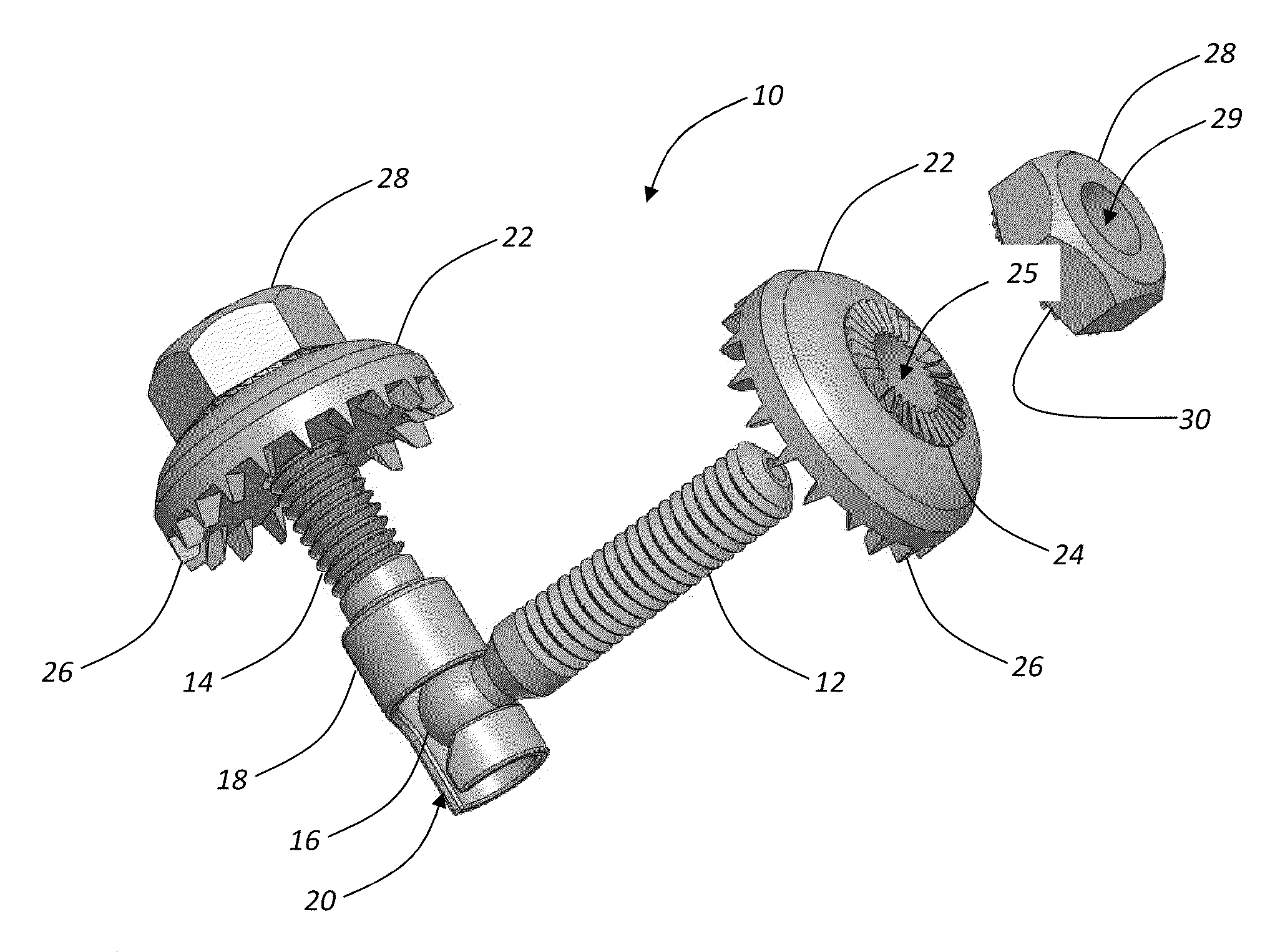
[0017]Referring now to FIG. 1, in one exemplary embodiment, the transfacet fixation assembly 10 of the present invention includes a cannulated engaging bolt 12 that is selectively coupled to and engaged with a cannulated receiving bolt 14 at an angle of between about 30 degrees and about 120 degrees, although other angles may of course be utilized. Each of the cannulated engaging bolt 12 and cannulated receiving bolt 14 is threaded and is configured to be disposed through a threaded or non-threaded hole or bore drilled through one of the bony structures making up a portion of the facet joint of a spine. It will be readily apparent to those of ordinary skill in the art that other anatomical joints may also be joined using the transfacet fixation assembly 10 of the present invention.

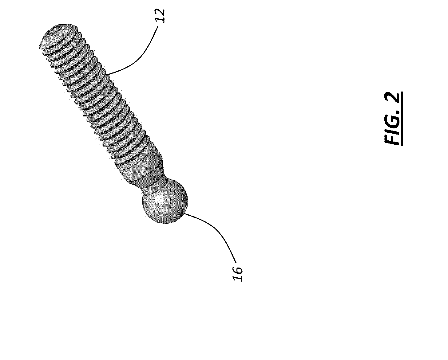
[0018]Referring now to FIGS. 2-4, in one exemplary embodiment, the cannulated engaging bolt 12 has a spherical distal end 16 (FIGS. 2 and 3) for engaging a locking sleeve 18 (FIGS. 3 and 4) disposed at the...


PUM


Abstract

The present invention provides a transfacet fixation assembly, including: an engaging bolt; and a receiving bolt selectively coupled to and engaged with the engaging bolt at an angle of between about 30 degrees and about 120 degrees; wherein each of the engaging bolt and the receiving bolt is configured to be disposed through a hole or bore formed through one of a plurality of bony structures making up a portion of a facet joint of a spine. Optionally, the engaging bolt includes a spherical distal end for engaging a locking sleeve disposed at a distal end of the receiving bolt.

Description

CROSS-REFERENCE TO RELATED APPLICATION[0001]The present non-provisional patent application claims the benefit of priority of U.S. Provisional Patent Application No. 61 / 061,694, filed on Jun. 16, 2008, and entitled “TRANSFACET FIXATION ASSEMBLY AND RELATED SURGICAL METHODS,” the contents of which are incorporated in full by reference herein.FIELD OF THE INVENTION[0002]The present invention relates generally to minimally invasive, surgically implantable spinal devices and systems. More specifically, the present invention relates to a transfacet fixation assembly that is used to immobilize a facet joint of the spine and related surgical methods. This transfacet fixation assembly is robust and flexible, such that it can be used with a variety of spinal morphologies.BACKGROUND OF THE INVENTION[0003]In the treatment of various spinal injuries, diseases, and degenerative conditions, it is desirable to immobilize a facet joint of the spine (e.g. in support of a spinal fusion) by means other...

Claims


Application Information

Patent Timeline
Patent Type & Authority Applications(United States)
IPC IPC(8): A61B17/70
CPCA61B17/7064
Inventor VARELA, ARMANDO
Owner CTL MEDICAL CORP
Why Eureka
Try Eureka