System and method to position and secure fractured bones

a fracture and bone technology, applied in the field of orthopedic surgery to repair fractured bones, can solve the problems of more devastating injury and major morbidity in the elderly population, and achieve the effect of facilitating longitudinal and latitudinal movemen

Inactive Publication Date: 2009-12-31
SPENCER JR EDWIN E
View PDF6 Cites 43 Cited by
  • Summary
  • Abstract
  • Description
  • Claims
  • Application Information

AI Technical Summary

Benefits of technology

[0005]In some embodiments, the present invention is a system for positioning and securing fractured bone parts including a fracture reduction plate and an elongated pin. In certain embodiments, the fracture reduction plate includes a body portion and a head portion. The body portion includes one or more distal screw holes and an elongated hole. The head portion includes one or more proximal locking screw holes having an inner diameter. In one embodiment, the proximal locking screw hole(s) facilitate longitudinal and latitudinal movement of the elongated pin in the proximal locking screw hole. A plurality of suture holes are located around a periphery of the head portion. The elongated pin includes a pin shaft having a distal portion and a proximal portion including a plurality of threads located on the pin shaft. In one embodiment, the pin shaft of the elongated pin has an outer diameter smaller than an inner diameter of the proximal locking screw hole.

Problems solved by technology

Like hip fractures, proximal humerus fractures are a major cause of morbidity in the elderly population.
In younger patients, high-energy trauma is a more frequent cause, and the resultant injury is more devastating.
At least one challenge associated with repairing proximal humerus fractures is the reduction of the fracture without stripping the surrounding tissue.
Another challenge facing surgeons is the challenge of holding the fracture in reduction while placing the fixation plate to secure the fracture.

Method used


Image

  • System and method to position and secure fractured bones
  • System and method to position and secure fractured bones
  • System and method to position and secure fractured bones

Examples


Embodiment Construction

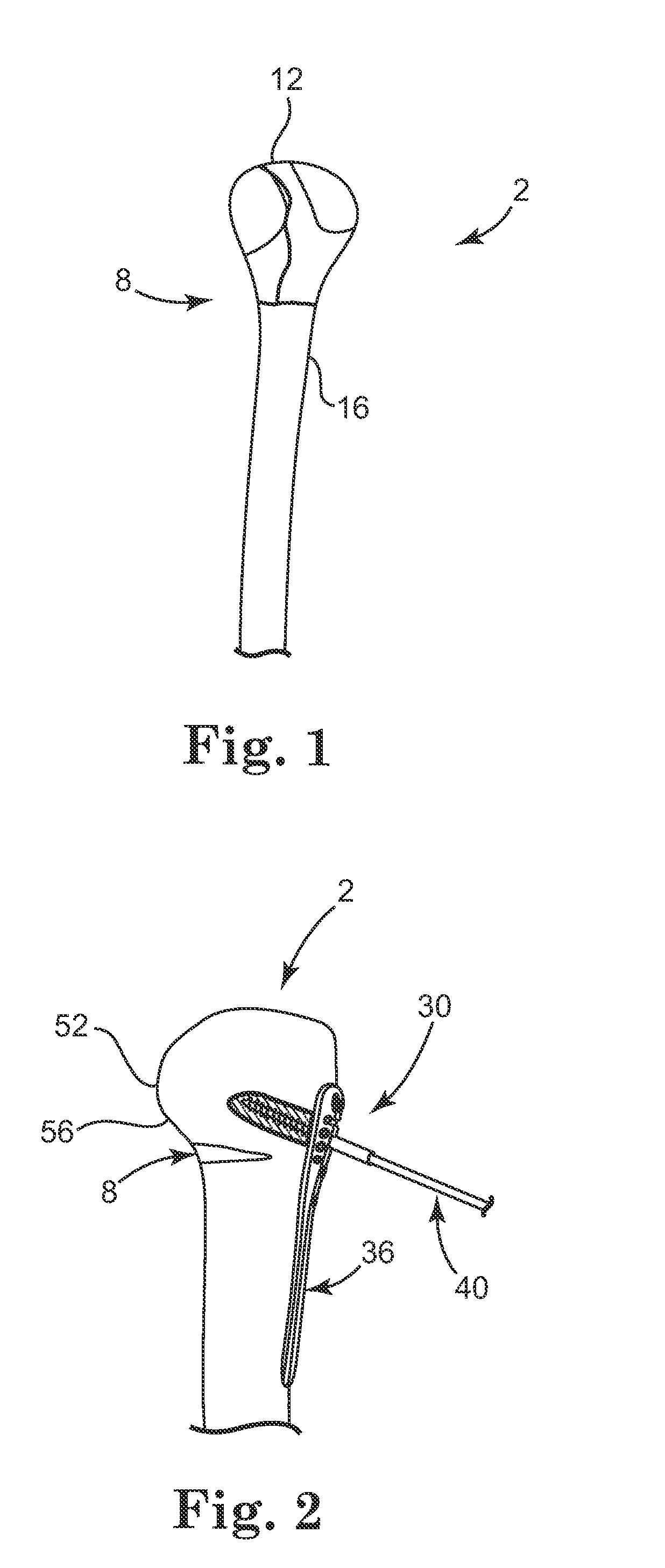
[0024]Proximal humerus fractures can be classified according to the Neer Classification System. The Neer Classification System includes 4 segments and also rates displacement and vascular isolation. The 4 segments are as follows: greater tuberosity (I), lesser tuberosity (II), humeral head (III), and shaft (IV). According to Neer, a fracture is displaced when there is more than 1 centimeter of displacement and 45° of angulation of any one fragment with respect to the others. Muscle pulls result in displacement. The supraspinatus and infraspinatus pull the greater tuberosity superiorly and the subscapularis pulls the lesser tuberosity medially, while the pectoralis major adducts the shaft medially.

[0025]Under the Neer Classification System, proximal humerus fractures may also be referred to as a two-part, a three-part, or a four-part fracture. Two-part fractures involve any of the four parts and include at least one fragment that is displaced. Three-part fractures include a displaced...


PUM


Abstract

A system and a method for reducing a proximal fractured humerus includes a fracture reduction plate and an elongated pin including a plurality of threads. The elongated pin is configured to be inserted through the fracture reduction plate and engage with a humeral head. The fracture reduction plate is placed on the fractured humerus and provisionally secured. Sutures may be used to guide the fracture reduction plate into place on the fractured humerus. Next, the elongated pin is engaged with the humeral head at a superior angle relative to the humerus and the fracture is reduced. The elongated pin may be used to push the humeral head in a superior direction while pulling on the humeral head using the sutures. The fracture reduction plate can then be secured to the humerus and the elongated pin removed. Bone graft material may be applied to the fracture reduction site.

Description

CROSS-REFERENCE TO RELATED APPLICATIONS[0001]This application claims the benefit of U.S. provisional application Ser. No. 61 / 024,327, filed Jan. 29, 2008, and entitled SYSTEM AND METHOD TO POSITION AND SECURE FRACTURED BONES, and U.S. provisional application Ser. No. 61 / 052,475, filed May 12, 2008, and entitled SYSTEM AND METHOD TO POSITION AND SECURE FRACTURED BONES, both of which are incorporated herein in their entirety by reference.TECHNICAL FIELD[0002]The present invention relates to orthopedic surgery to repair fractured bones. More particularly, the present invention relates to systems and methods for repairing proximal humeral head fractures.BACKGROUND[0003]Proximal humerus fractures have been estimated conservatively to account for 5% of all fractures. These fractures occur primarily in older patients, many of whom suffer from osteoporosis. Like hip fractures, proximal humerus fractures are a major cause of morbidity in the elderly population. The most common mechanism for ...

Claims


Application Information

Patent Timeline
Patent Type & Authority Applications(United States)
IPC IPC(8): A61B17/66A61B17/88
CPCA61B17/06166A61B17/8866A61B17/86A61B17/8061
Inventor SPENCER, JR., EDWIN E.
Owner SPENCER JR EDWIN E
Why Eureka
Try Eureka