Vehicle Roof Mount Antenna

a technology for roof mounts and vehicles, applied in antennas, antenna details, movable bodies, etc., can solve the problems of vehicle roof deformation, inability to ensure waterproofness and dustproofness, and the deformation of vehicle roof becomes more prominent, so as to achieve satisfactory waterproofness and dustproofness

Active Publication Date: 2010-01-14
HARADA IND CO LTD
View PDF101 Cites 14 Cited by
  • Summary
  • Abstract
  • Description
  • Claims
  • Application Information

AI Technical Summary

Benefits of technology

[0019]In the vehicle roof mount antenna according to the present invention, the pressing force of the annular rib against the vehicle roof, which is applied when the annular rib is brought into press contact with the vehicle roof, can be reduced. Thus, even when the vehicle roof on which the roof mount antenna device is mounted has a small thickness, it is possible to prevent the vehicle roof from being deformed while ensuring waterproofness and dustproofness. Further, satisfactory waterproofness and dustproofness can be ensured even when the vehicle roof mount antenna is mounted on a vehicle roof having a curved surface shape.

Problems solved by technology

When the pressing force is excessively large, a problem that the vehicle roof is deformed arises.
Further, when the installation pressure of the boss is reduced so as not to cause the deformation of the vehicle roof, the waterproofness and the dustproofness which are the intended functions of the annular rib cannot be ensured satisfactorily.
Therefore, the problem of the deformation of the vehicle roof has become more prominent.
In particular, there is a gap between the annular rib that is away from the boss and the vehicle roof, so that satisfactory waterproofness and dustproofness cannot be ensured.

Method used


Image

  • Vehicle Roof Mount Antenna
  • Vehicle Roof Mount Antenna
  • Vehicle Roof Mount Antenna

Examples


first embodiment

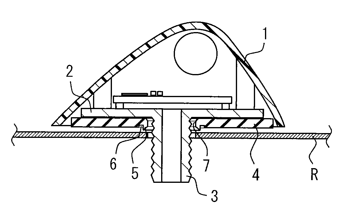
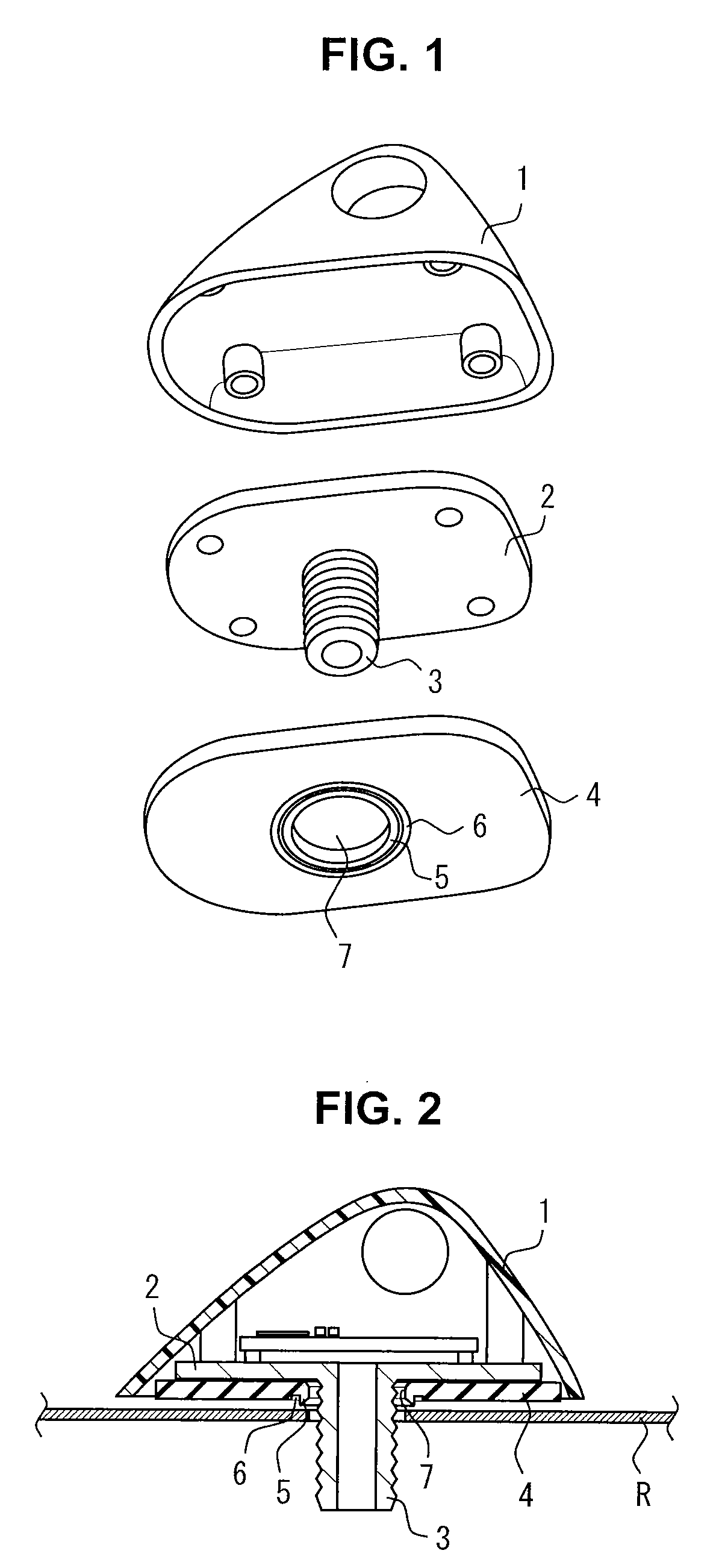
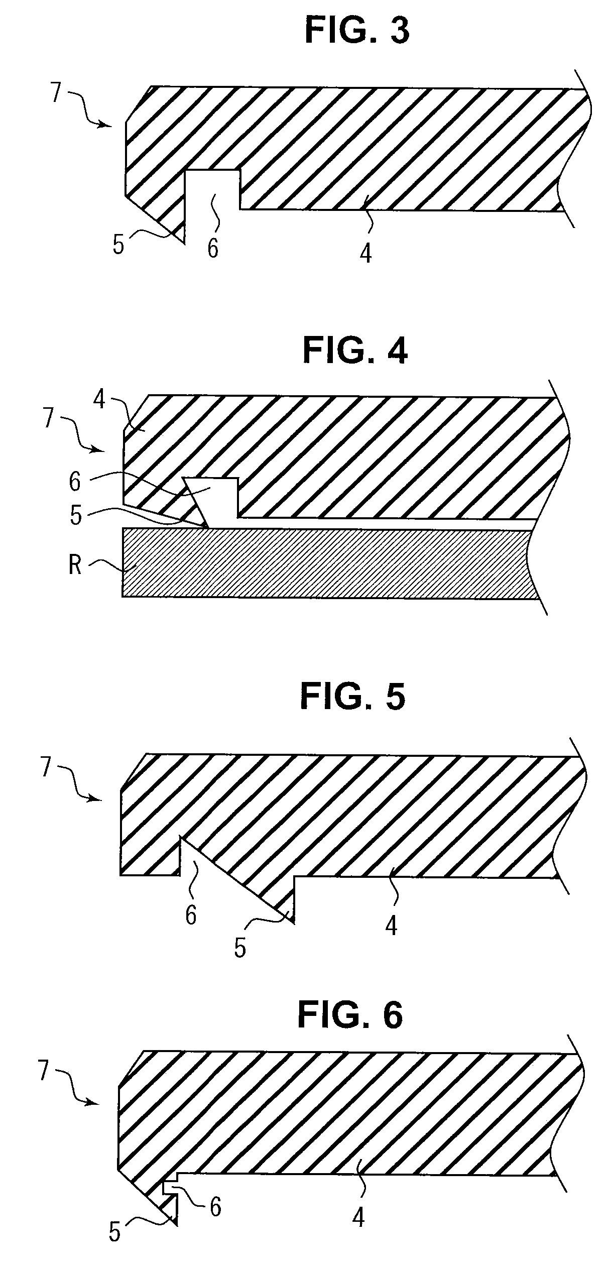
[0038]With reference to FIG. 3, a more detailed structure of the vehicle roof mount antenna according to the present invention will be described. FIG. 3 is a partially enlarged view showing the annular rib and the annular groove portion provided around the boss hole in the vehicle roof mount antenna according to the As shown in FIG. 3, the annular rib 5 is provided at the periphery of the boss hole 7. The annular groove portion 6 is provided at the outer peripheral edge of the annular rib 5. In the example shown in the drawings, the annular rib 5 has a cross-section of a shed roof shape as viewed in the direction perpendicular to the surface of the pad 4 on the vehicle roof R side. In the case where the annular rib 5 has the shed roof shape having an inclined surface inclined toward the boss hole 7 side, when the annular rib 5 is brought into press contact with the vehicle roof 5, it is crushed to be deformed toward the peripheral edge of the pad 4.

[0039]A pressing force correspond...

second embodiment

[0050]Although the second rib 9 is provided continuously from the first groove portion 11 in the vehicle roof mount antenna shown in FIG. 9, the present invention is not limited to this, but the second rib 9 may be provided at a position apart from the first groove portion. However, in the case where the second rib is provided continuously from the first groove portion as shown in FIG. 9, the first groove portion serves as an escape margin for the first rib, as well as the length of the second rib from its base to tip can be increased. That is, in this case, two effects can be produced with a single groove (first groove portion), making it possible to reduce the pressing force against the vehicle roof.

[0051]Although both the first and the second ribs 8 and 9 have a cross-section of the shed roof shape as viewed in the direction perpendicular to the surface of the pad 4 on the vehicle roof R side in FIG. 9, they may have another shape such as one shown in FIG. 7 or FIG. 8. Further, ...


PUM


Abstract

The vehicle roof mount antenna to be detachably mounted on a vehicle roof is mainly constituted by an antenna cover 1, an antenna base 2, a boss 3, a pad 4, an annular rib 5, and an annular groove portion 6. The pad 4 has a boss hole 7 through which the boss 3 penetrates and is disposed between the antenna base 2 and the vehicle roof R. The annular rib 5, which is made of an elastic material, is provided on the vehicle roof R side surface of the pad 4. When the vehicle roof mount antenna is fixed to the vehicle roof R, the annular rib 5 is inclined from the boss hole 7 toward a periphery of the pad 4. The annular groove portion 6 is provided at a position where the pressing force of the annular rib 5 against the vehicle roof R can be reduced.

Description

RELATED APPLICATION[0001]This application relates to and claims priority from Japanese Patent Application No. 2008-178412 filed on Jul. 8, 2008.BACKGROUND OF THE INVENTION[0002]1. Field of the Invention[0003]The present invention relates to a vehicle roof mount antenna detachably mounted on a vehicle roof, and more particularly to a vehicle roof mount antenna improving waterproofness and dustproofness.[0004]2. Description of the Related Art[0005]A vehicle roof mount antenna typically has a pad on a contact surface with a vehicle roof. The pad has an annular rib (flange) made of an elastic material so as to improve waterproofness and dustproofness. The installation pressure of a boss brings the annular rib of the pad into press contact with the vehicle roof, thereby ensuring the waterproofness and dustproofness of the vehicle roof mount antenna.[0006]For example, Patent Document 1 (Japanese Patent Application Kokai Publication No. 2005-102031) discloses an antenna for an automobile. ...

Claims


Application Information

Patent Timeline
Patent Type & Authority Applications(United States)
IPC IPC(8): H01Q1/32B60R11/02H01Q1/22
CPCH01Q1/3275H01Q1/1214H01Q1/22H01Q1/32H01Q5/00
Inventor KOBAYASHI, HIDEKAZUMINAKAWA, MITSUOOBA, SATOSHIHAYASHI, MAKOTOYOKOYAMA, TOSHIRO
Owner HARADA IND CO LTD
Why Eureka
Try Eureka