
Positive locking mechanism for USB connected devices

a technology of usb connector and locking mechanism, which is applied in the direction of coupling device connection, coupling parts engagement/disengagement, electrical apparatus, etc., can solve the problems of inadvertent disconnect of handheld devices, no locking mechanism used for securing connection,

Active Publication Date: 2010-01-21
DEARBORN GROUP TECH
View PDF8 Cites 10 Cited by
  • Summary
  • Abstract
  • Description
  • Claims
  • Application Information

AI Technical Summary

Problems solved by technology

However, with typical USB connectors, there is no locking mechanism used for securing the connection between the connector and the connector's corresponding port.
Therefore, certain types of handheld devices, such as PDAs or diagnostic tools, which are used and moved around quite frequently, can become inadvertently disconnected from the USB connector.

Method used


Image

  • Positive locking mechanism for USB connected devices
  • Positive locking mechanism for USB connected devices
  • Positive locking mechanism for USB connected devices

Examples


Embodiment Construction

[0013]The following description of the preferred embodiment(s) is merely exemplary in nature and is in no way intended to limit the invention, its application, or uses.

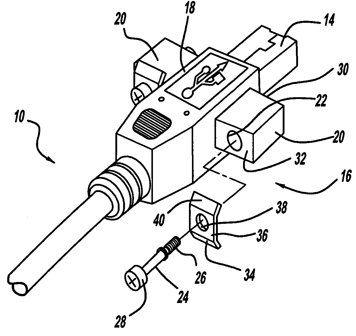
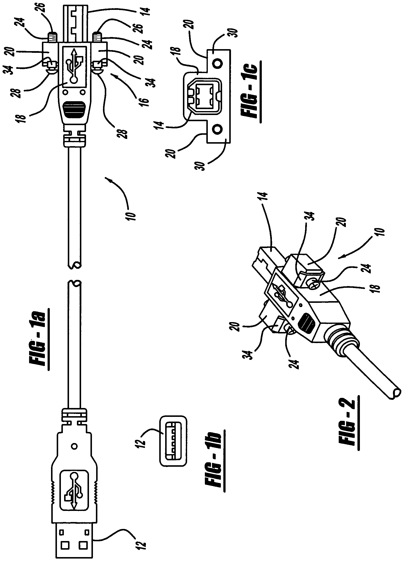
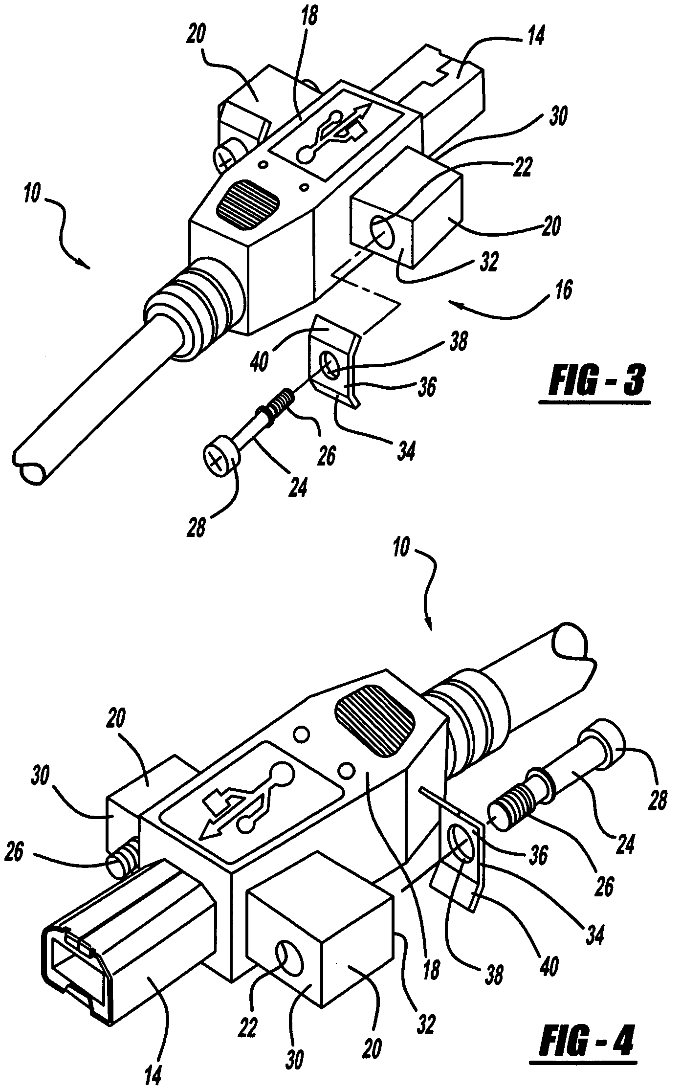
[0014]A universal serial bus (USB) connector cable incorporating a positive locking mechanism according to the present invention is shown in the Figures generally at 10. The cable 10 includes two different types,of standard connectors, the standard “A connector”12, and the standard “B connector”14, with the exception that a positive locking mechanism, according to the present invention and generally shown at 16, is incorporated into the B connector 14. The A connector is typically connected to a computer (not shown) and the B connector 14 is typically connected to a device (not shown) which is used for communicating with the computer.

[0015]The operation of the USB cable 10 is similar any other standard USB cable, and therefore is not described herein. The B connector 14 includes a protective molding 18. A portion of t...


PUM


Abstract

The present invention is a positive locking mechanism for a universal serial bus (USB) connector which includes at least one mounting portion connected to the USB connector with the mounting portion having an aperture. The present invention also includes at least one flange in proximity to the mounting portion, with the flange having an aperture, as well as a fastener inserted through the aperture of the flange and the aperture of the mounting portion, where the fastener is used to connect the mounting portion to a structure.

Description

FIELD OF THE INVENTION[0001]The present invention relates to universal serial bus (USB) connectors. More particularly, the present invention relates to a positive locking mechanism for a USB connector for securing a USB connector to a device used for communicating with a computer.BACKGROUND OF THE INVENTION[0002]USB connectors and cables are generally known. There are two common types of USB connectors. One type of connector is called an “A connector,” and the other type of connector is what is referred to as a “B type connector.” The first type of connector, an A connector, is used for heading “upstream” toward the computer, and the second type of connector, the B connector, heads “downstream” and connects to an individual device used for communicating with the computer. These types of connectors are used to allow various external devices, such as printers, scanners, fax machines, keyboards, a mouse, a personal digital assistant (PDA), and other devices to communicate with the comp...

Claims


Application Information

Patent Timeline
Patent Type & Authority Applications(United States)
IPC IPC(8): H01R13/62
CPCH01R13/6215
Inventor BLANTON, ROBINELSLANDER, ROGER LEON VAN
Owner DEARBORN GROUP TECH
Learn More