Control surface of aircraft

a control surface and aircraft technology, applied in the direction of aircraft stabilisation, wing adjustment, wings, etc., can solve the problems of increasing the aerodynamic drag not allowing an increase in the control power, and lack of stiffness of the secondary element of the control surface, so as to achieve a greater effective curvature

Inactive Publication Date: 2010-01-28
AIRBUS OPERATIONS SL
View PDF0 Cites 24 Cited by
  • Summary
  • Abstract
  • Description
  • Claims
  • Application Information

AI Technical Summary

Benefits of technology

[0008]Thus, the present invention relates to a double-hinged control surface for an aircraft lifting surface, in particular for a stabilizer surface, said control surface comprising a primary control surface and a secondary control surface, with the secondary control surface only partially occupying the span of the primary control surface, the primary control surface being moved, either by means of a torsion bar integral with said primary control surface, said torsion bar being actuated by one or more actuator elements located within the fuselage of the aircraft, or by means of actuators positioned behind the rear spar of the lifting surface, with the secondary control surface rotating about a hinge axis fixed relative to the primary control surface, in its turn said secondary control surface being connected mechanically to the lifting surface via one or more connecting elements, in such a way that the movement of the secondary control surface is linked kinematically to the movement of the primary control surface, so that the rotation of the secondary control surface takes place in the same sense as that of the primary control surface, thus achieving an increase in the control power, i.e. the aerodynamic force produced by the control surface in its entirety.
[0009]Moreover, in the double-hinged control surface for an aircraft lifting surface according to the present invention, the length of the secondary control surface along its hinge axis is significantly less than the length of the primary control surface, and moreover the width or chord of said secondary control surface narrows significantly along the direction of its hinge axis and towards the tip of the lifting surface, resulting in a very advantageous distribution of aerodynamic load on the lifting surface, thus achieving a greater effective curvature in the inner zone, near the fuselage, of the control surface and therefore a higher angle of stall of aerodynamic lift by deflection of the control surface.

Problems solved by technology

The problem that arises with such control surfaces is that they do not allow an increase in the control power, i.e. the aerodynamic force produced by the control surface, in fact they reduce it as they reduce the effective curvature of the airfoil.
This configuration gives rise to problems of stalling of the lifting surface when the angle of attack thereon is high, as well as problems resulting from the lack of stiffness of the secondary element of the control surface.
The problem arising with this configuration, which is for example that used for the rudder of the Boeing 777, is that the jump in effective curvature on deflection of the secondary surface produces a vortex of separated airflow that increases the aerodynamic drag of the control surface.

Method used


Image

  • Control surface of aircraft
  • Control surface of aircraft
  • Control surface of aircraft

Examples


Embodiment Construction

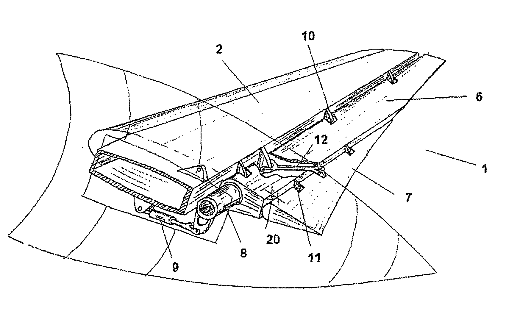
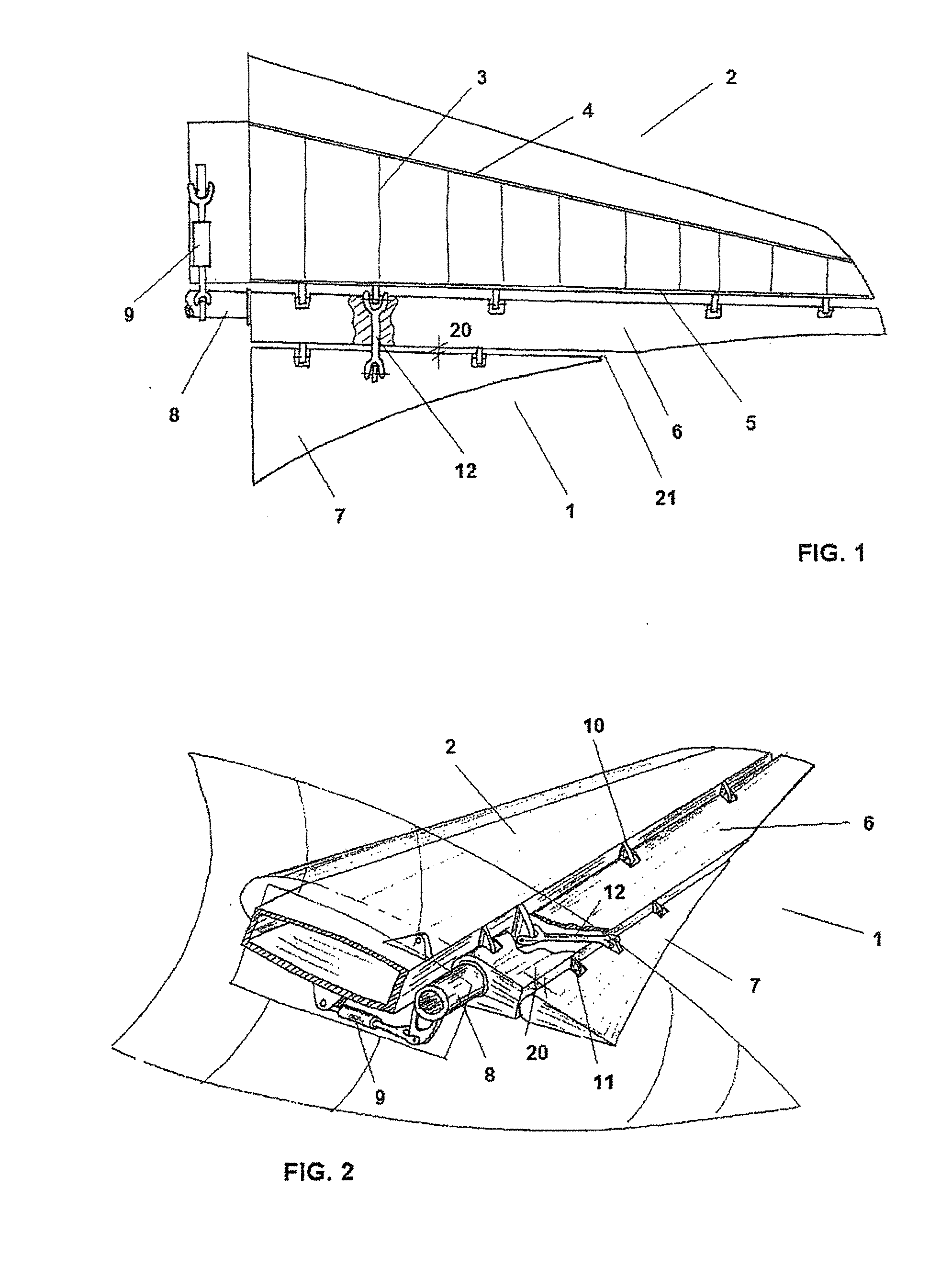
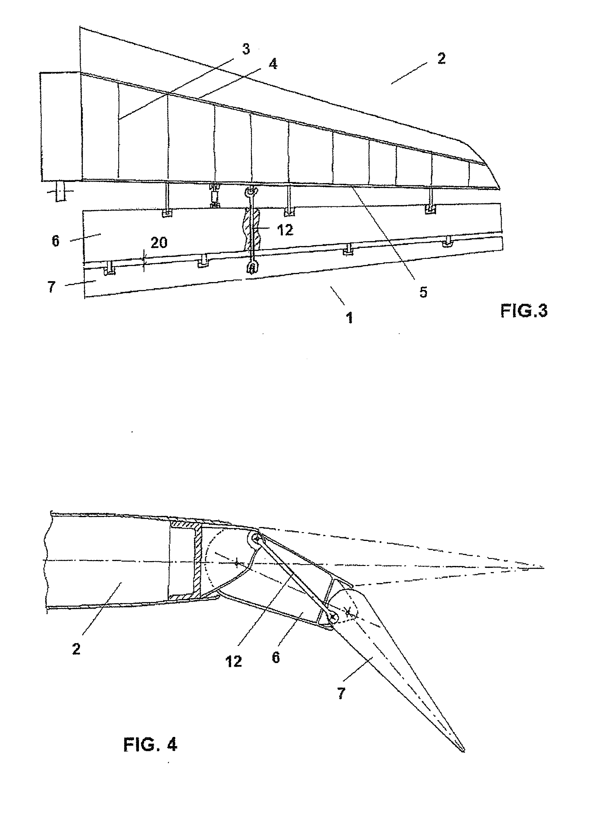
[0015]In a preferred embodiment, the present invention relates to a control surface 1, with double hinges 10 and 11, for an lifting surface 2 of an aircraft, in particular for a stabilizer surface, that comprises ribs 3, rear spar 5 and front spar 4, said control surface 1 comprising a primary control surface 6 that comprises in its turn a hinge axis 10, and a secondary control surface 7, that comprises in its turn a hinge axis 11, with the secondary control surface 7 only partially occupying the span of the primary control surface 6, the primary control surface 6 being moved by means of a torsion bar 8 integral with said primary control surface 6, said torsion bar 8 being actuated by one or more actuator elements 9 located within the fuselage of the aircraft, or alternatively by means of actuators (not shown) positioned between the rear spar 5 and the primary control surface 6, with the secondary control surface 7 rotating about its hinge axis 11 fixed relative to the primary contr...


PUM


Abstract

Aircraft control surface (1), in particular for an aircraft lifting surface (2), that comprises a primary control surface (6) that comprises a hinge axis (10), and a secondary control surface (7) that comprises a hinge axis (11), with the secondary control surface (7) rotating by means of its hinge axis (11) relative to the primary control surface (6), said secondary control surface (7) only partially occupying the span of the primary control surface (6), the length of the secondary control surface (7) along its hinge axis (11) being significantly less than the length of the primary control surface (6) along its hinge axis (10), and moreover the width or chord of said secondary control surface (7) along the direction of its hinge axis (11) narrows significantly towards the tip of the lifting surface (2) according to a law of narrowing designed expressly for adapting the distribution of torsional stiffness along the span of the lifting surface (2) to the distribution of aerodynamic load thereon, whereas the distribution of effective curvature due to the deflection of said control surface (1) is such that it increases the stalling angle of the lifting surface (2).

Description

FIELD OF THE INVENTION[0001]The present invention relates to a configuration of control surface of aircraft, in particular to a control surface for an aircraft stabilizer surface.BACKGROUND OF THE INVENTION[0002]The lifting surfaces of an aircraft, mainly the wings and the stabilizers, comprise control surfaces (flaps, ailerons, slats and spoilers in the wings and rudders and elevators in the stabilizers) that are movable parts capable of exerting various effects on the flight of said aircraft. The commonest configuration of these control surfaces is that of a simple hinge, in such a way that the control surface rotates relative to the lifting surface on which it is arranged.[0003]Advanced designs of control surfaces for aircraft lifting surfaces are known, called double-hinged, in which the control surfaces comprise two surfaces, a primary control surface and a secondary control surface, movable relative to one another and relative to the lifting surface of the aircraft.[0004]Thus,...

Claims


Application Information

Patent Timeline
Patent Type & Authority Applications(United States)
IPC IPC(8): B64C5/10
CPCB64C9/00B64C9/10B64C9/04B64C9/02
Inventor LLAMAS SANDIN, RAUL CARLOSSANZ MARTINEZ, PABLO TIMOTEO
Owner AIRBUS OPERATIONS SL
Why Eureka
Try Eureka