Hinge mechanism and automotive luggage board structure using the same

a technology of automotive luggage board and hinge mechanism, which is applied in the direction of wing accessories, manufacturing tools, roofs, etc., can solve the problems of increasing the weight of the structure, apprehension that the rotation of the spacer board and the spring member may be hindered by a relative position, and the complexity of the member

Active Publication Date: 2010-02-04
MEIWA IND CO LTD
View PDF4 Cites 62 Cited by
  • Summary
  • Abstract
  • Description
  • Claims
  • Application Information

AI Technical Summary

Problems solved by technology

However, in such a conventional technology, the hinge recessed groove as a rotation center of the spacer board and a center shaft as a rotation center of the spring member are located at positions different from each other, and accordingly, there is an apprehension that rotations of the spacer board and the spring member may be hindered by a relative positional shift of both thereof, which occurs at the time when both thereof make the rotations.
However, in order to slidably engage the tip end of the arm of the spring member with the auxiliary board, it is n

Method used


Image

  • Hinge mechanism and automotive luggage board structure using the same
  • Hinge mechanism and automotive luggage board structure using the same
  • Hinge mechanism and automotive luggage board structure using the same

Examples


first embodiment

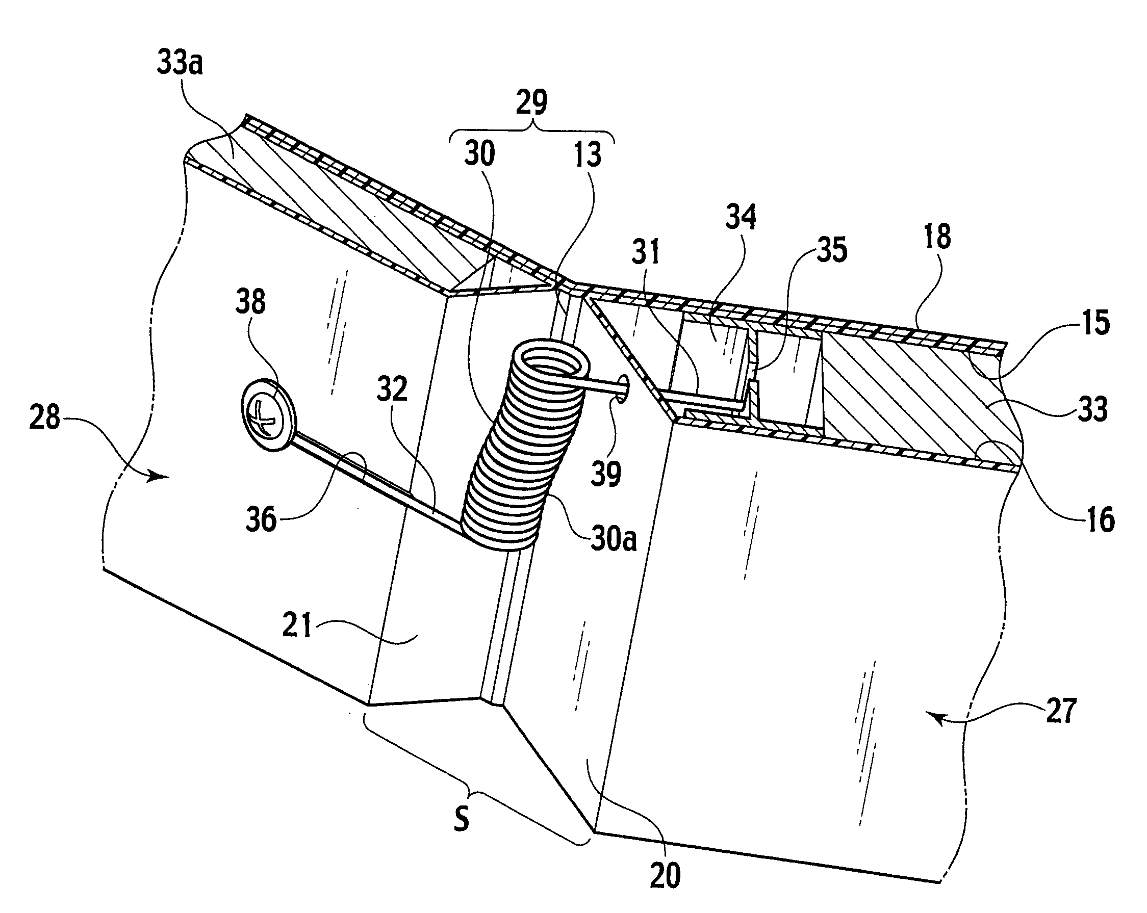
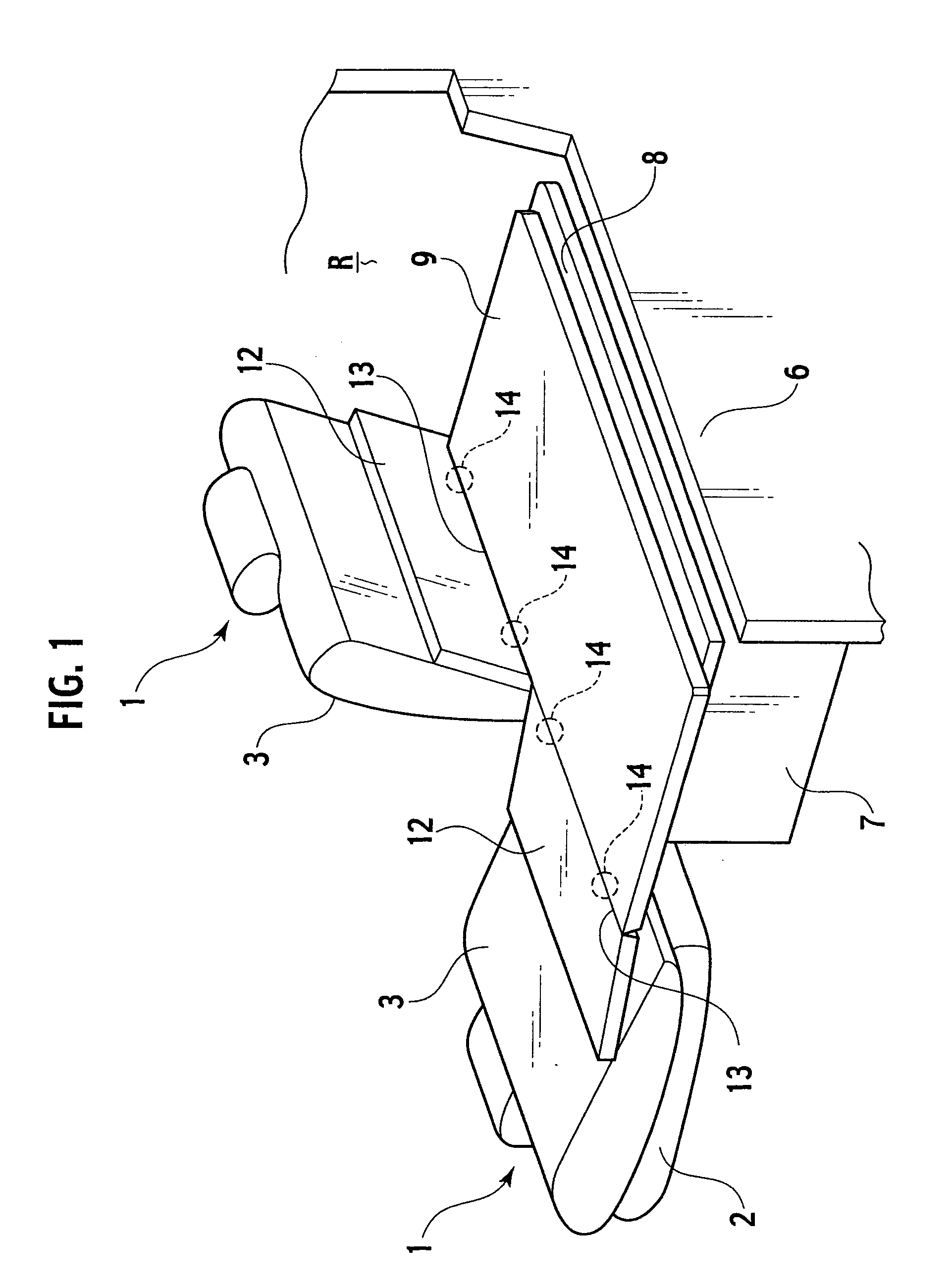
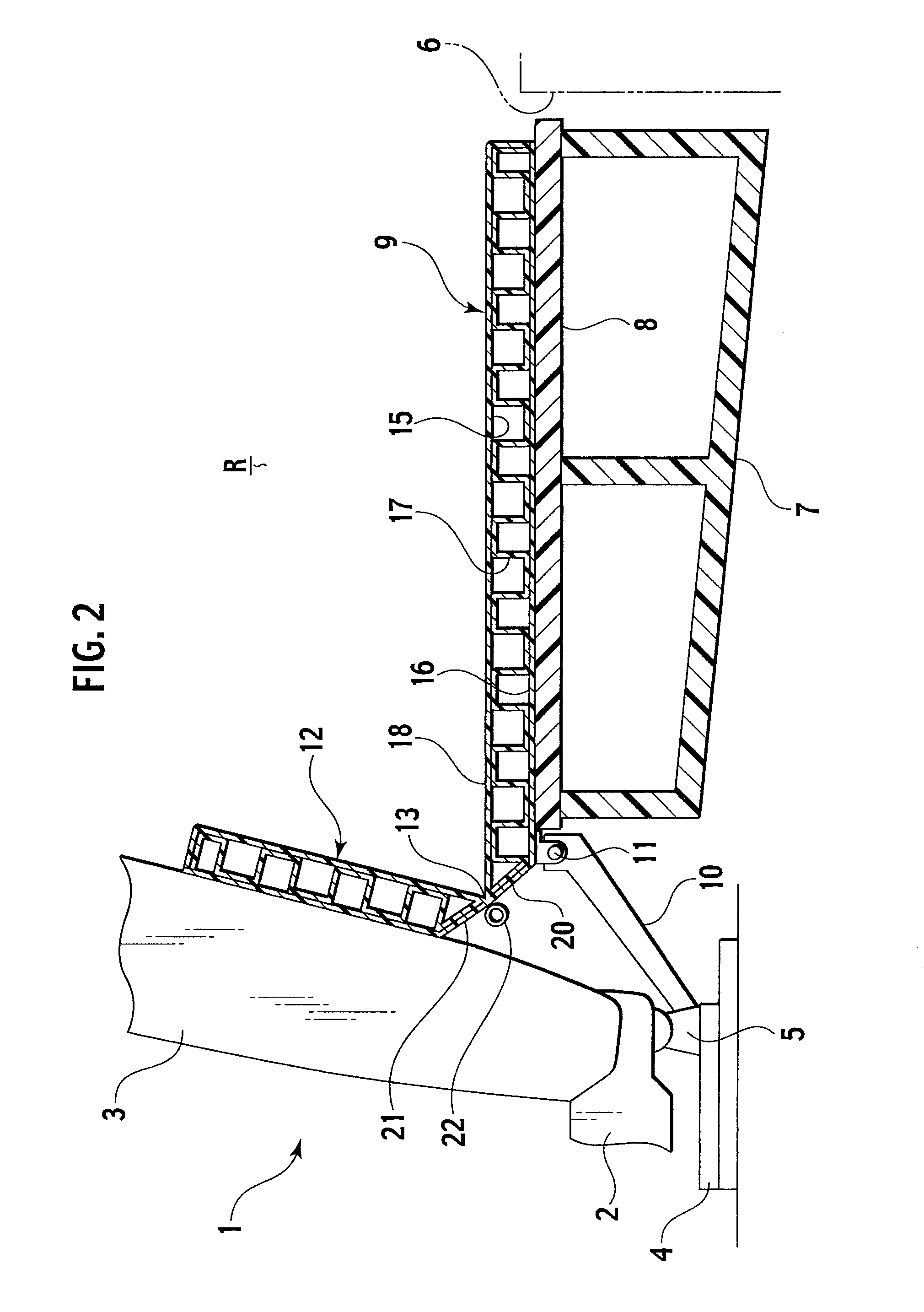
[0027]FIG. 1 is a perspective view showing a luggage board structure according to this embodiment, FIG. 2 is a cross-sectional view showing a luggage board and an auxiliary board in a normal state where a rear seat back is erected, FIG. 3 is a cross-sectional view showing the luggage board and the auxiliary board, showing a case where the rear seat back is in a forward tilted state, FIG. 4 is a perspective view showing a coil spring in an inside of a space portion, FIG. 5 is an exploded perspective view showing a structure of the luggage board, FIG. 6 is a cross-sectional view showing a vicinity of an integral hinge in an erected state of the auxiliary board, and FIG. 7 is a cross-sectional view showing the vicinity of the integral hinge in a forward tilted state of the auxiliary board.

[0028]A right and left pair of rear seats 1 are placed on a rear side of a vehicle cabin inside of an automobile. The rear seats 1 include rear seat cushions 2 and rear seat backs 3. In this embodimen...

second embodiment

[0052]FIG. 8 is a cross-sectional view showing a luggage board and an auxiliary board in a case where a rear seat back according to this embodiment is in a normal state, FIG. 9 is a cross-sectional view showing the luggage board and the auxiliary board in a case where the rear seat back according to this embodiment is in a forward tilted state, FIG. 10 is a perspective view showing a coil spring in a space portion according to this embodiment, FIG. 11 is an exploded perspective view showing a structure of the luggage board according to this embodiment, FIG. 12 is a cross-sectional view showing a vicinity of an integral hinge in an erected state of the auxiliary board according to this embodiment, and FIG. 13 is a cross-sectional view showing the vicinity of the integral hinge in a forward tilted state of the auxiliary board according to this embodiment. Note that this embodiment includes similar constituents to those of the above-mentioned first embodiment. Hence, common reference n...


PUM


Abstract

A hinge mechanism 29 that rotatably provides a luggage board 27 and an auxiliary board 28 continuously with each other while interposing an integral hinge 13 therebetween, in which a space portion S is provided between mutually opposite end surfaces 20 and 21 of the luggage board 27 and the auxiliary board 28, wherein a restoring force generation portion 30a of a spring member 30 is housed in the space portion S, and in addition, both end portions 31 and 32 of the spring member 30 are fixed to the luggage board 27 and the auxiliary board 28, respectively.

Description

TECHNICAL FIELD[0001]The present invention relates to a hinge mechanism and an automotive luggage board structure using the same.BACKGROUND ART[0002]A luggage room is formed between a rear seat back of an automobile and a back door thereof. This luggage room is made expandable by tilting forward the rear seat back provided so as to be tiltable forward. Then, a luggage board is provided on a bottom surface of the luggage room.[0003]As heretofore disclosed in Japanese Patent Laid-Open Publication No. 2003-118500, as a luggage board structure, a structure has been known, in which a hinge recessed groove is additionally provided on a spacer board that is attached to a front edge portion of a luggage floor trim and hides a gap between the luggage floor trim and a rear seat, and a spring member is attached to the hinge recessed groove so that a front half portion of the spacer board can sag in up and down directions from the hinge recessed groove taken as a base point, and so that a front...

Claims


Application Information

Patent Timeline
IPC IPC(8): B60R5/04E05F1/10
CPCB60R5/04B60R5/044Y10T16/593E05F1/1215E05D3/02E05F1/10F16C11/04F16C11/12
Inventor JOURAKU, TAKESHI
Owner MEIWA IND CO LTD
Why Eureka
Try Eureka