AI technical title is built by Patsnap AI team. It summarizes the technical point description of the patent document.
a compact accelerator and accelerator technology, applied in the field of linear accelerators, can solve the problems of affecting beam quality and performance, overall device less than optimal for the intended use of accelerating charged particles, and limited use of beams
Inactive Publication Date: 2010-02-11
LAWRENCE LIVERMORE NAT SECURITY LLC
View PDF19 Cites 18 Cited by
Summary
Abstract
Description
Claims
Application Information
AI Technical Summary
This helps you quickly interpret patents by identifying the three key elements:
Problems solved by technology
Method used
Benefits of technology
Benefits of technology
[0011]One aspect of the present invention includes a compact accelerator system comprising: a support structure; an integrated particle generator-accelerator actually mounted on the support structure, comprising: a compact linear accelerator having at least one transmission line(s) extending toward a transverse acceleration axis; and a charged particle generator connected to the compact linear accelerator for producing and injecting a charged particle beam into the compact linear accelerator along the acceleration axis; switch means connectable to a high voltage potential for propagating at least one electrical wavefront(s) through the transmission line(s) of the compact linear accelerator to impress a pulsed gradient along the acceleration axis which imparts energy to the injected beam; and means for actuating the integrated particle generator-accelerator to control the pointing direction of the energized beam and the position of the beamspot produced thereby.
Problems solved by technology
The existing dielectric wall accelerators, such as the Carder DWA, however, have certain inherent problems which can affect beam quality and performance.
In particular, several problems exist in the disc-shaped geometry of the Carder DWA which make the overall device less than optimum for the intended use of accelerating charged particles.
Instead, a charged particle beam traversing the electric field created by such a structure will receive a time varying energy gain, which can prevent an accelerator system from properly transporting such beam, and making such beams of limited use.
The disc-shaped Blumlein structure of Carder can cause excessive levels of electrical energy to be stored in the system.
Such excess energy can have a detrimental effect on the performance and reliability of the overall device, which can lead to premature failure of the system.
This problem is further compounded when long acceleration pulses are required since the output pulse length of this disc-shaped Blumlein structure is directly related to the radial extent from the central hole.
As the preferred embodiment of initiating the switch is the use of a laser or other similar device, a highly complex distribution system is required.
Moreover, a long pulse structure requires large dielectric sheets for which fabrication is difficult.
This can also increase the weight of such a structure.
While some of the long pulse disadvantages can be alleviated by the use of spiral grooves in all three of the conductors in the asymmetric Blumlein, this can result in a destructive interference layer-to-layer coupling which can inhibit the operation.
Method used
Image
Click on the blue label to locate the original text in one second.
Reading with bidirectional positioning of images and text.
Examples
Embodiment Construction
[0041]A. Compact Accelerator with Strip-Shaped Blumlein
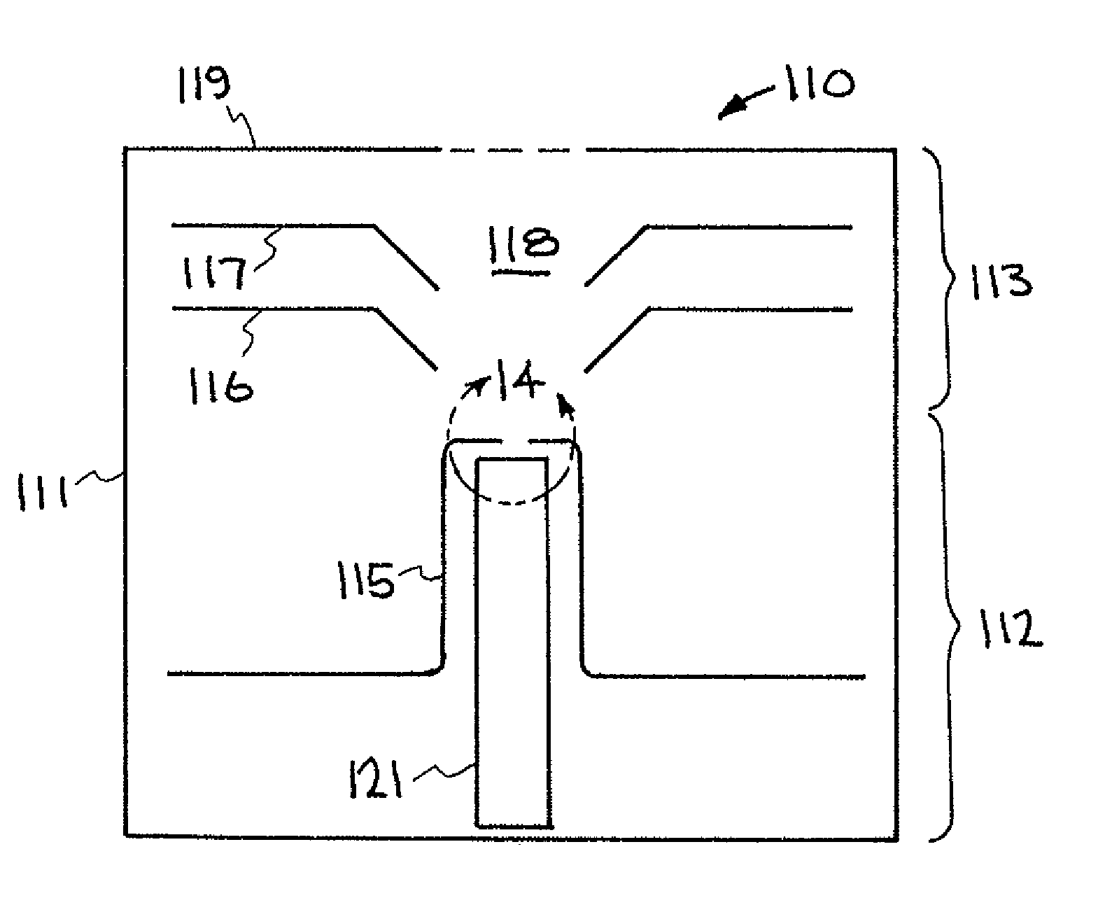
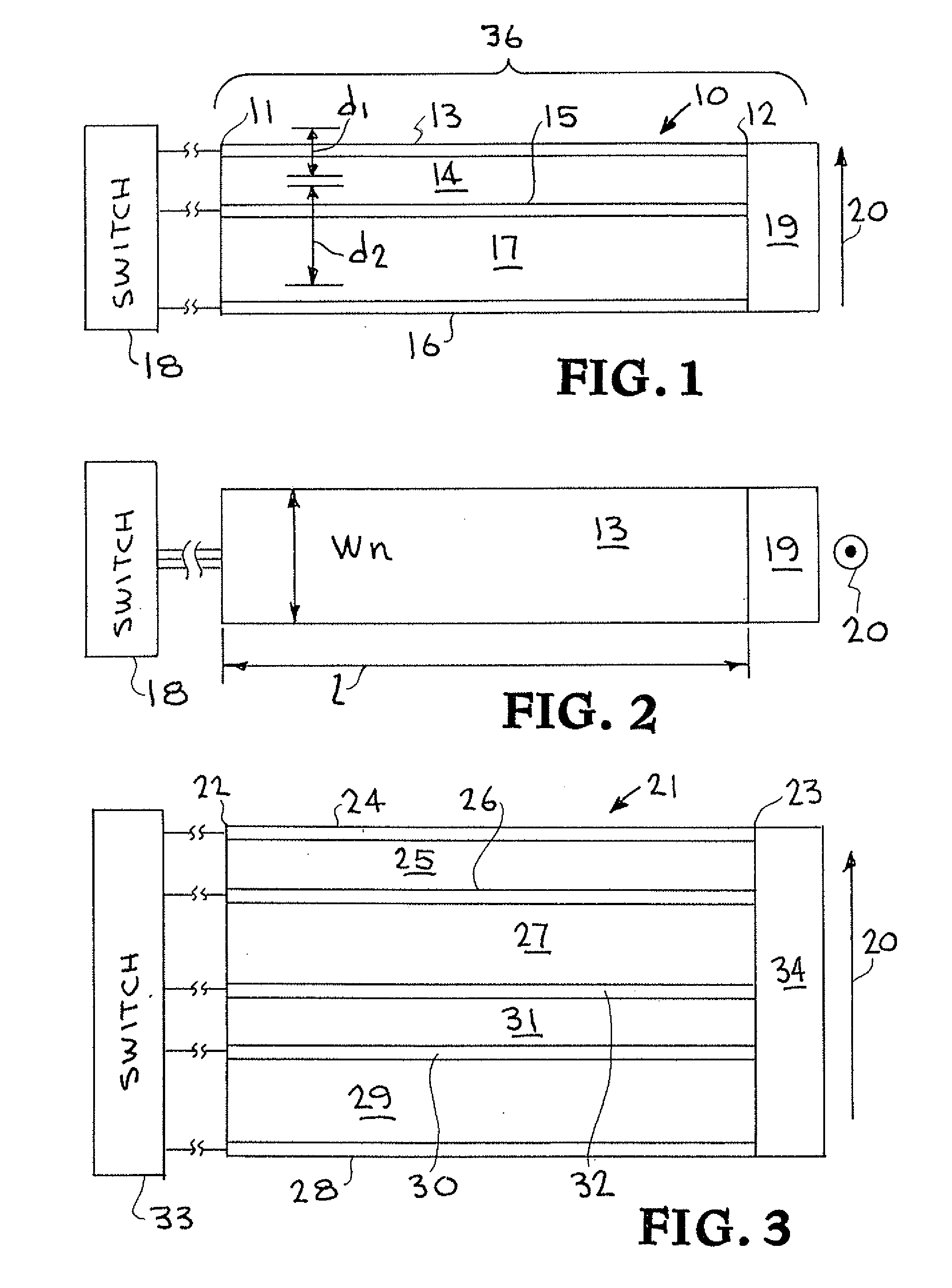
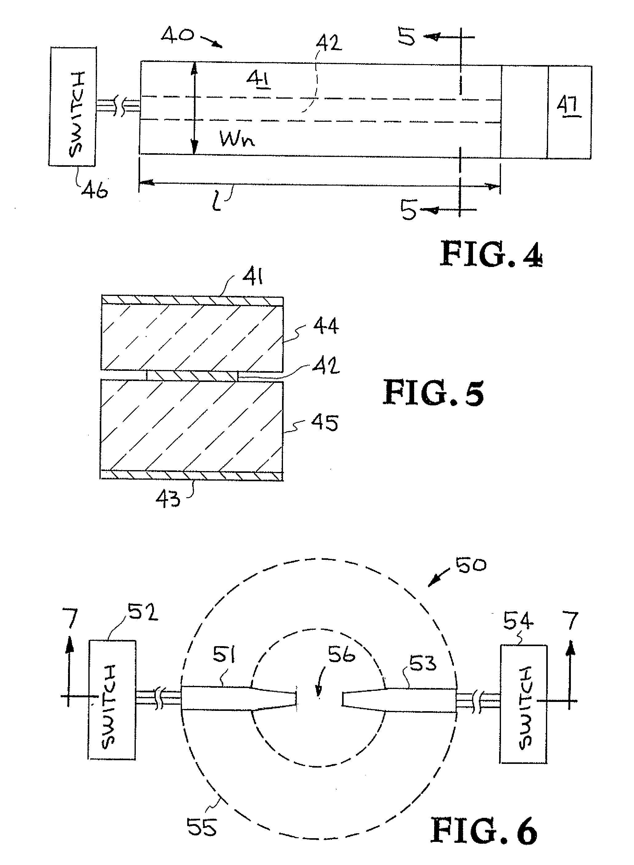
[0042]Turning now to the drawings, FIGS. 1-12 show a compact linear accelerator used in the present invention, having at least one strip-shaped Blumlein module which guides a propagating wavefront between first and second ends and controls the output pulse at the second end. Each Blumlein module has first, second, and third planar conductor strips, with a first dielectric strip between the first and second conductor strips, and a second dielectric strip between the second and third conductor strips. Additionally, the compact linear accelerator includes a high voltage power supply connected to charge the second conductor strip to a high potential, and a switch for switching the high potential in the second conductor strip to at least one of the first and third conductor strips so as to initiate a propagating reverse polarity wavefront(s) in the corresponding dielectric strip(s).
[0043]The compact linear accelerator has at least on...
PUM
Abstract
A compact accelerator system having an integrated particle generator-linear accelerator with a compact, small-scale construction capable of producing an energetic (˜70-250 MeV) proton beam or other nuclei and transporting the beam direction to a medical therapy patient without the need for bending magnets or other hardware often required for remote beam transport. The integrated particle generator-accelerator is actuable as a unitary body on a support structure to enable scanning of a particle beam by direction actuation of the particle generator-accelerator.
Description
I. REFERENCE TO PRIOR APPLICATIONS[0001]This application is a divisional of application Ser. No. 11 / 586,378, filed Oct. 24, 2006, which claims the benefit of prior application Ser. No. 11 / 036,431, filed Jan. 14, 2005, which claims the benefit of Provisional Application No. 60 / 536,943, filed Jan. 15, 2004; and this application also claims the benefit of U.S. Provisional Application Nos. 60 / 730,128, 60 / 730,129, and 60 / 730,161, filed Oct. 24, 2005, and U.S. Provisional Application No. 60 / 798,016, filed May 4, 2006, all of which are incorporated by reference herein.STATEMENT AS TO RIGHTS TO INVENTIONS MADE UNDER FEDERALLY SPONSORED RESEARCH AND DEVELOPMENT[0002]The United States Government has rights in this invention pursuant to Contract No. DE-ACS2-07NA27344 between the United States Department of Energy and Lawrence Livermore National Security, LLC for the operation of Lawrence Livermore National Laboratory.II. FIELD OF THE INVENTION[0003]The present invention relates to linear accel...
Claims
Application Information
Patent Timeline
Application Date:The date an application was filed.
Publication Date:The date a patent or application was officially published.
First Publication Date:The earliest publication date of a patent with the same application number.
Issue Date:Publication date of the patent grant document.
PCT Entry Date:The Entry date of PCT National Phase.
Estimated Expiry Date:The statutory expiry date of a patent right according to the Patent Law, and it is the longest term of protection that the patent right can achieve without the termination of the patent right due to other reasons(Term extension factor has been taken into account ).
Invalid Date:Actual expiry date is based on effective date or publication date of legal transaction data of invalid patent.
Patent Type & AuthorityApplications(United States)
IPC IPC(8): H01J3/14H01J27/00
CPCH01J27/26H05H9/02H05H7/02
InventorCAPORASO, GEORGE J.CHEN, YU-JIUANHAWKINS, STEVEN A.SAMPAYAN, STEPHEN E.

