
Method of Forming Magnetic Blocks and Equipment for Carrying Out That Method
a technology of magnetic blocks and equipment, applied in the direction of magnet materials, cores/yokes, water/sludge/sewage treatment, etc., can solve the problems of reducing rapidly and the handling of magnets in a magnetized state is therefore considerably more complicated
- Summary
- Abstract
- Description
- Claims
- Application Information
AI Technical Summary
Benefits of technology
Problems solved by technology
Method used
Image

Examples
example 1
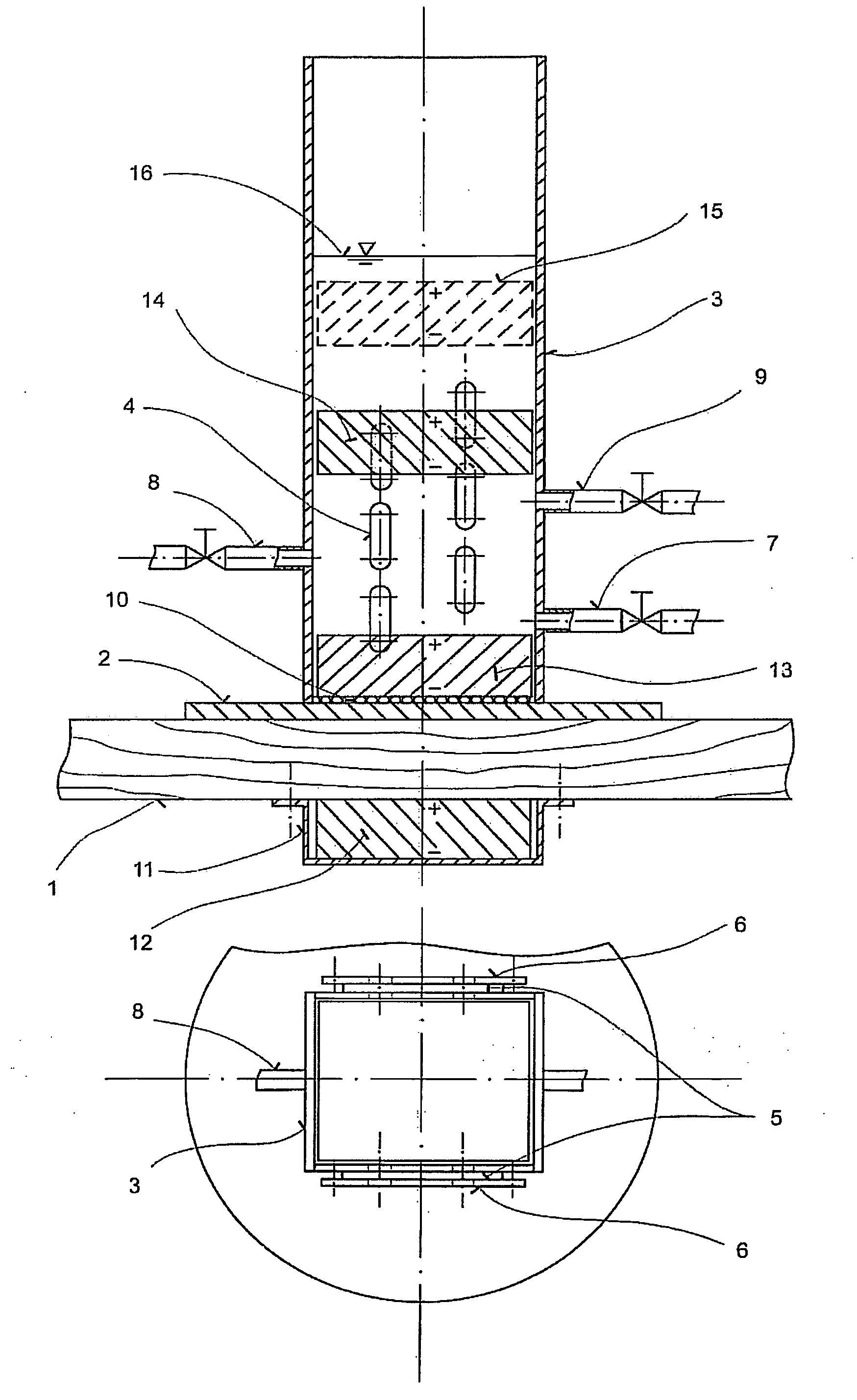
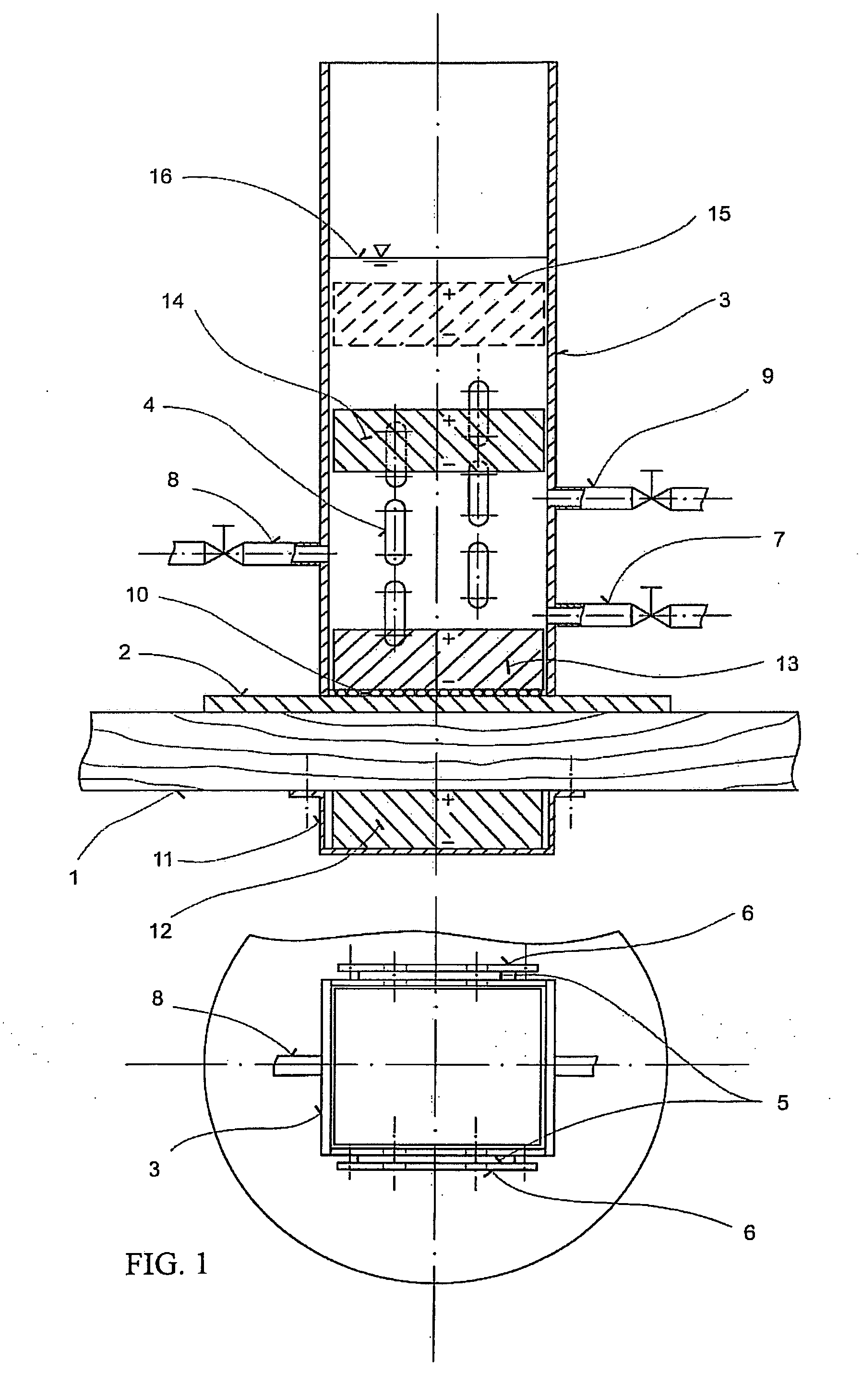
[0029]The basic embodiment of the equipment for carrying out the method of forming or assembling large magnetic blocks is illustrated in the attached drawing. The equipment in this embodiment is designed for assembling smaller magnets or magnetic plates into larger blocks and was verified by assembling blocks of individual NdFeB magnets with a maximum energy product (BH)max equal to 350 kJ / m3 and with ground-plan dimensions of 0.5×0.05 m and a height of 0.03 m. This equipment placed on a work board 1 of non-magnetic material (e.g. wood) consists of a vessel the bottom of which consists of a non-magnetic stainless steel bottom plate 2 to which is welded the vessel housing 3 (tube), also of non-magnetic stainless steel. The interior transverse section of the vessel corresponds to the outer transverse section of the assembled magnets, or of the magnetic plates (the drawing shows, in top view, a rectangular cross-section, but it can also be square, round etc.). In the course of assembly...
example 2
[0030]For the assembly of dimensionally bigger, industrially scaled large magnetic blocks from individual magnetic plates, a larger embodiment of the above mentioned equipment is required. This embodiment was designed and executed for the gradual assembly of individual magnetic plates with ground-plan dimensions of 0.16×0.11 m and a height of 0.03 m into large magnetic blocks of the same ground-plan dimensions and a height of up to 0.12 m. Each plate is composed of six NdFeB magnets with dimensions of 0.05×0.05×0.03 m. In the lateral walls of the vessel, instead of one socket with valve or slide valve, at a certain height from the bottom there are two opposing sockets, symmetrical with respect to the vertical axis of the vessel, both sockets being arranged at the same height. The sockets are connected to a slide valve or valve, through a T fitting, by long hoses of the same length, making it possible to close and regulate the flow of liquid, hydraulic oil. Through regulation, this s...
PUM
| Property | Measurement | Unit |
|---|---|---|
| height | aaaaa | aaaaa |
| height | aaaaa | aaaaa |
| height | aaaaa | aaaaa |
Abstract
Description
Claims
Application Information