Method of forming magnetic blocks and equipment for carrying out that method

a technology of magnetic blocks and equipment, applied in the direction of magnet materials, cores/yokes, water/sludge/sewage treatment, etc., can solve the problems of reducing rapidly and the handling of magnets in a magnetized state is therefore considerably more complicated

Inactive Publication Date: 2010-09-14
USTAV STRUKTURY A MECHANIKY HORNIN AV CR V V I
View PDF2 Cites 0 Cited by
  • Summary
  • Abstract
  • Description
  • Claims
  • Application Information

AI Technical Summary

Benefits of technology

[0007]The basis of the invention lies in the fact that, during formation of the magnetic blocks, a first permanent magnet is lowered to the bottom of an upwardly open vessel, the vessel is then filled with liquid and, while forcefully maintaining the first permanent magnet in that position, further permanent magnets are gradually inserted into the vessel in a direction perpendicular to their resulting joint contact surfaces, where the adjacent surfaces of the superimposed permanent magnets always have an opposite polarity, whilst during insertion of a further permanent magnet, the liquid is drained from the space in the vessel under that inserted magnet, whereby the motion speed of the inserted magnet is controlled as it bears down on the permanent magnet lying beneath it.
[0009]The magnets or magnetic plates approach each other at a controlled speed in a direction perpendicular to the resulting joint contact surface that is parallel to the magnetic flux lines passing through that contact surface. By comparison with known procedures, the solution according to this invention makes possible a significant reduction in manpower requirements for assembling the large magnetic blocks, a shortening of the work time needed and increased safety levels, whilst at the same time achieving very good magnetic parameters in the assembled large magnetic blocks.
[0011]Practical control of the method for forming magnetic circuits from NdFeB magnets using a method and equipment according to this invention permits the construction of magnetic filters in which it is possible to attain high values of magnetic induction in the separating zone. It involves simple, relatively inexpensive equipment, operating in a discontinuous cyclic mode with regular workforce requirements. Significantly stronger magnetic fields are formed than has been the case so far with the new types of permanent magnets in a larger volume separating zone.
[0012]Sockets with regulating valves can be arranged in pairs, both sockets of each pair being arranged at the same height. The tendency for the magnets or magnetic plates to jam in the vessel is thus limited.
[0014]The permanent magnet can be in the form of a panel whose peripheral frame incorporates several partial permanent magnets. It is thus possible to create large magnetic blocks for industrial use.
[0016]Shaped non-magnetic plates can be inserted between the walls of the vessel and the permanent magnets to permit the removal of the magnetic block from the vessel, which makes it possible to free the magnets in the vessel in case they get jammed and also facilitates the removal from the vessel of both the individual magnets and the whole magnetic block.

Problems solved by technology

In all of these devices with magnets of rare earth, a high value of magnetic induction is achieved directly on the surface of the rollers, drums, plates or rods, diminishing rapidly, however, with increasing distance from the surface.
Handling them in a magnetized state is therefore considerably more complicated than is the case with ferrite magnets.

Method used


Image

  • Method of forming magnetic blocks and equipment for carrying out that method
  • Method of forming magnetic blocks and equipment for carrying out that method

Examples


example 1

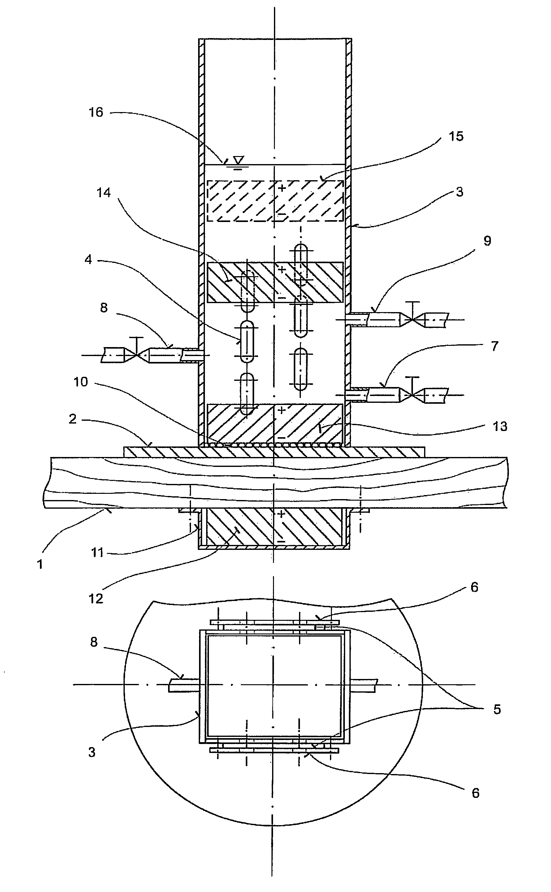
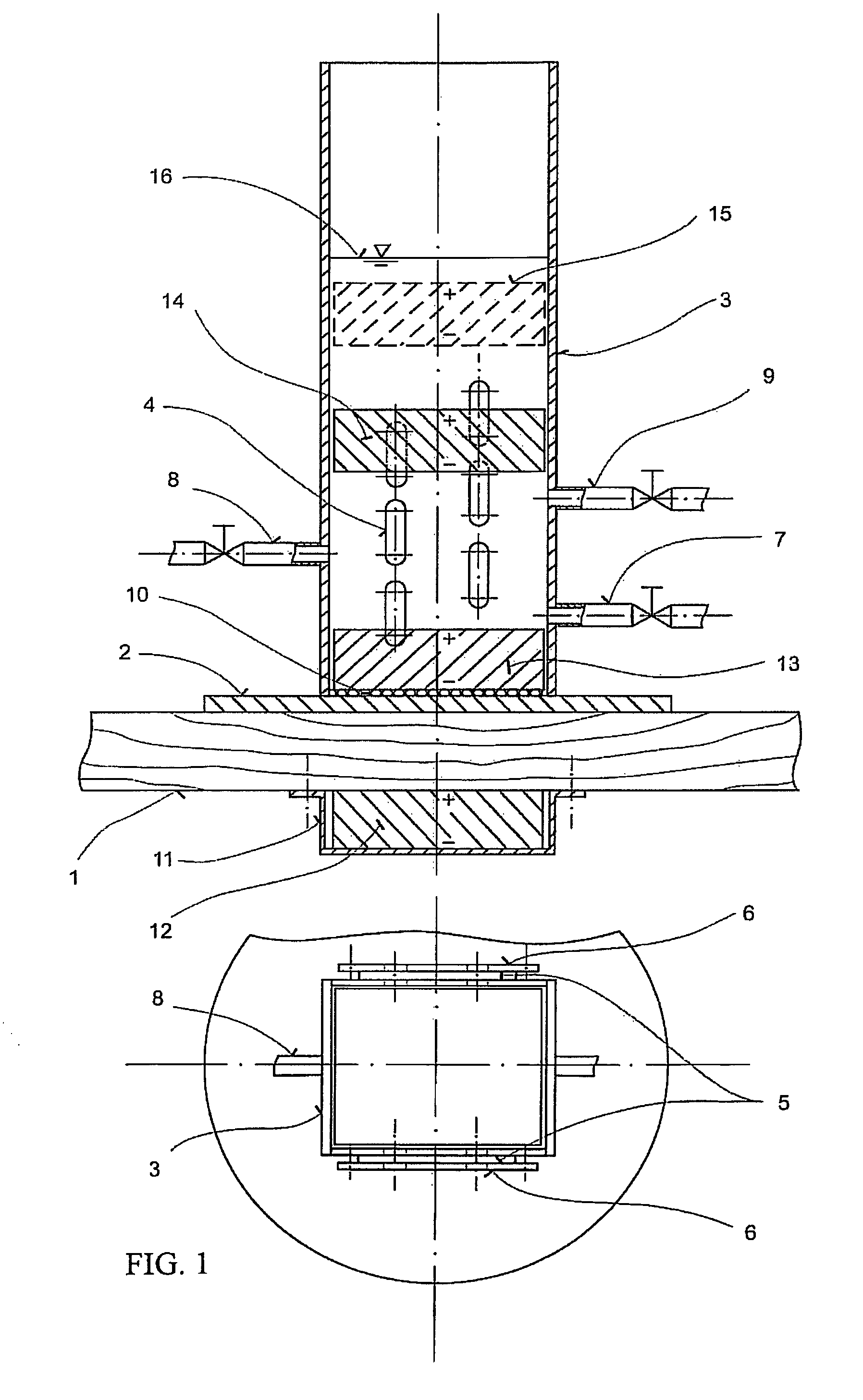
[0029]The basic embodiment of the equipment for carrying out the method of forming or assembling large magnetic blocks is illustrated in the attached drawing. The equipment in this embodiment is designed for assembling smaller magnets or magnetic plates into larger blocks and was verified by assembling blocks of individual NdFeB magnets with a maximum energy product (BH)max equal to 350 kJ / m3 and with ground-plan dimensions of 0.5×0.05 m and a height of 0.03 m. This equipment placed on a work board 1 of non-magnetic material (e.g. wood) consists of a vessel the bottom of which consists of a non-magnetic stainless steel bottom plate 2 to which is welded the vessel housing 3 (tube), also of non-magnetic stainless steel. The interior transverse section of the vessel corresponds to the outer transverse section of the assembled magnets, or of the magnetic plates (the drawing shows, in top view, a rectangular cross-section, but it can also be square, round etc.). In the course of assembly...

example 2

[0030]For the assembly of dimensionally bigger, industrially scaled large magnetic blocks from individual magnetic plates, a larger embodiment of the above mentioned equipment is required. This embodiment was designed and executed for the gradual assembly of individual magnetic plates with ground-plan dimensions of 0.16×0.11 m and a height of 0.03 m into large magnetic blocks of the same ground-plan dimensions and a height of up to 0.12 m. Each plate is composed of six NdFeB magnets with dimensions of 0.05×0.05×0.03 m. In the lateral walls of the vessel, instead of one socket with valve or slide valve, at a certain height from the bottom there are two opposing sockets, symmetrical with respect to the vertical axis of the vessel, both sockets being arranged at the same height. The sockets are connected to a slide valve or valve, through a T fitting, by long hoses of the same length, making it possible to close and regulate the flow of liquid, hydraulic oil. Through regulation, this s...


PUM

PropertyMeasurementUnit
heightaaaaaaaaaa
heightaaaaaaaaaa
heightaaaaaaaaaa

Abstract

In forming magnetic blocks, a first permanent magnet may be lowered to the bottom of an upwardly open vessel, the vessel may be already filled or may be then filled with liquid and, while forcefully maintaining the first permanent magnet in that position, further permanent magnets are gradually inserted into the vessel in a direction perpendicular to their resulting joint contact surfaces, where the adjacent surfaces of the superimposed permanent magnets have an opposite polarity, while during insertion of a further permanent magnet, the liquid is drained from the space in the vessel under that inserted magnet, whereby the motion speed of the inserted magnet is controlled as it bears down on the permanent magnet lying beneath it. The equipment for carrying out the method may comprise a vessel whose interior cross-section corresponds with clearance to the outline of the assembled permanent magnets, where sockets with regulating valves may be arranged along the height of the vessel, spaced so that their lower edges always lie above the upper surfaces of the assembled permanent magnets, and where all the parts are of non-magnetic material, while the bottom of the vessel may be furnished with a means for exerting an attractive force on the lowered permanent magnets.

Description

FIELD OF THE INVENTION[0001]The invention involves a method of forming magnetic blocks from individual permanent magnets or compact magnetic plates, composed of several permanent magnets made of a material whose maximum energy product (BH)max is considerably higher than in ferritic magnets, and equipment for carrying out that method.DESCRIPTION OF THE PRIOR ART[0002]Magnetic circuits with permanent magnets assembled into large magnetic blocks are used in various branches of industry. A wide application is found for example in the construction of magnetic filters for filtering ceramic casting materials and glazes, in various types of magnetic separators for treating mineralogical raw materials, for the separation of ferromagnetic impurities from various materials (for example, during the treatment of vitreous bodies, plastic materials, waste from auto wreckage treatment) etc. Large magnetic blocks imbedded in those devices were hitherto composed in particular of permanent ferrite mag...

Claims


Application Information

Patent Timeline
Patent Type & Authority Patents(United States)
IPC IPC(8): H01F7/00B01D35/06B01D35/00B01D35/14B03C1/02B03C1/30C02F1/48H01F3/00H01F7/02H01F1/00
CPCH01F7/0294H01F41/0253
Inventor T
Owner USTAV STRUKTURY A MECHANIKY HORNIN AV CR V V I
Why Eureka
Try Eureka