Differential Device

a differential device and solenoid technology, applied in mechanical actuation clutches, gearing, transportation and packaging, etc., can solve the problems of improper positioning of solenoid, inability to establish electric connection with electric power source installed on stationary members, and inability to bear the reaction force of solenoid in response to actuation, etc., to achieve simple but reliable structure

Active Publication Date: 2010-03-04
GKN DRIVELINE TORQUE TECHNOLOGY KK
View PDF8 Cites 29 Cited by
  • Summary
  • Abstract
  • Description
  • Claims
  • Application Information

AI Technical Summary

Benefits of technology

[0010]An object of the present invention is to provide a differential device having a simple but reliable structure in light of support of a solenoid.

Problems solved by technology

How to combine the stationary solenoid with the rotating differential and how to properly position the solenoid relative to the differential are technical issues.
A factor of the issues is that, whereas the differential rotates, the solenoid must be stationary.
The reason is that otherwise an electric connection with an electric power source installed on a stationary member cannot be established and the solenoid cannot bear reaction force in response to actuation.
When the gap fluctuates, energy loss will occur.

Method used


Image

  • Differential Device
  • Differential Device
  • Differential Device

Examples


first embodiment

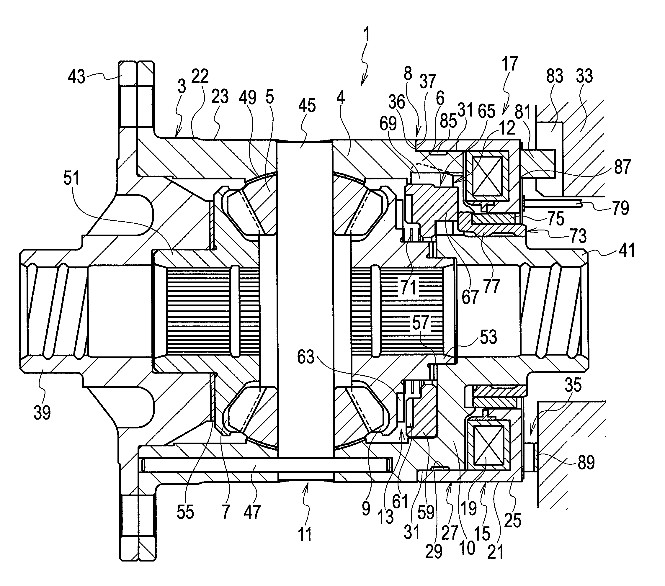
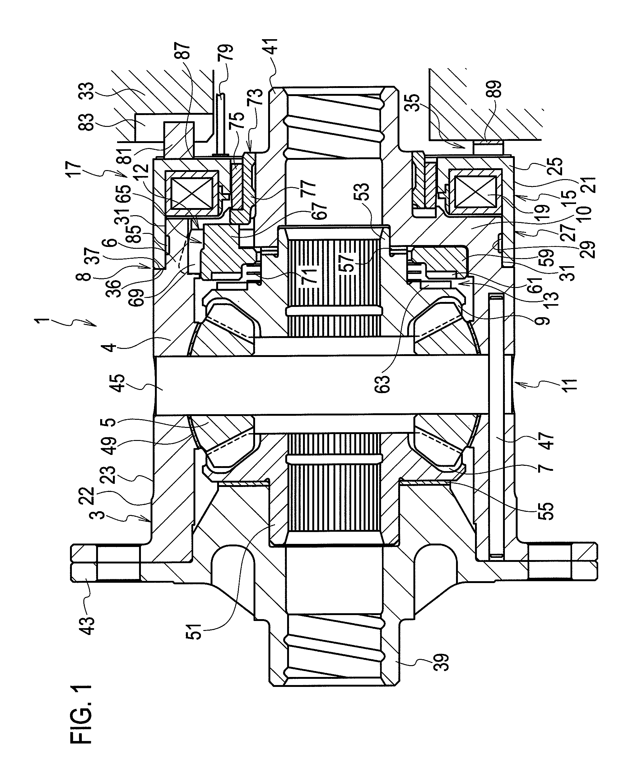
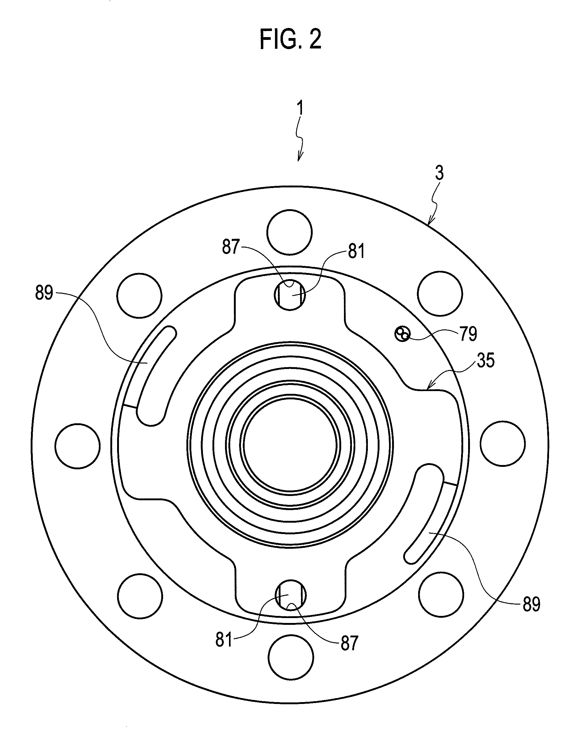
[0020]FIGS. 1 and 2 illustrate a differential device 1 for differentially distributing a driving force generated by an engine to right and left axles in accordance with a first embodiment of the present invention. The differential device 1 is comprised of a differential case 3 which receives the driving force to rotate about an axis, a differential gear set 11 housed in the case 3, a clutch 13 for engaging with the differential gear set 11 to lock differential motion thereof, and an actuator 17 for actuating the clutch 13.

[0021]The differential case 3 is drivingly coupled with the differential gear set 11 and therefore the differential gear set 11 along with the differential case 3 rotates about the axis of the case 3. The differential case 3 is in general made up of a right end wall 10, a left end wall opposed to the right end wall 10, and a side wall 4 generally formed in a cylindrical shape, so as to define a chamber therein for housing the differential gear set 11. Right and lef...

second embodiment

[0040]Referring to FIG. 3, a second embodiment of the present invention will be described hereinafter.

[0041]A differential device 101 in accordance with the second embodiment has a structure similar to that of the aforementioned differential device 1 as the same reference numerals are attached to FIG. 3. The following description will be mainly given to differences from the aforementioned first embodiment.

[0042]The end of the magnetic core 25 on the outer periphery of the coiled wire 19 ends up around the left end of the coiled wire 19. Instead of the elongation like as the first embodiment, a sleeve portion 103 once formed in a separate body is fixed to, bonded with, fused with, or united with the end of the magnetic core 25.

[0043]Any hardening treatment may be executed on the inner periphery 105 as with the case of the first embodiment. Because the sleeve portion 103 is formed in a separate body, area limitation of such a treatment can be easily done. Therefore the present embodim...

third embodiment

[0045]Referring to FIG. 4, a third embodiment of the present invention will be described hereinafter.

[0046]A differential device 201 in accordance with the third embodiment has a structure similar to those of the aforementioned differential devices 1 and 101 as the same reference numerals are attached to FIG. 4. The following description will be mainly given to differences from the aforementioned first and second embodiments.

[0047]In the differential device 201, a positioning means 205 is provided. The positioning means 205 is comprised of a secured projection 209 projectingly secured with the boss portion of the right boss portion 41, and a contact member 207 engaging with both the positioning member 205 and the right end of the magnetic core 25, thereby positioning the solenoid 15 in the axial direction. The secured projection 209 may be made of any non-magnetic material so as to reduce leakage of magnetism to the case 3.

[0048]The aforementioned structure facilitates the installat...


PUM


Abstract

A differential device differentially distributes a driving force to first and second axles. The differential device is comprised of a differential gear set configured to allow differential motion between the first and second axles, a casing rotatable about an axis, the casing housing and being drivingly coupled with the differential gear set and including a first end wall, a second end wall axially opposed to the first end wall, and a side wall disposed radially outward, which in combination with the first end wall and the second end wall defines a chamber configured to house the differential gear set, a clutch engageable with the differential gear set, a solenoid configured to drive the clutch, which is disposed adjacent to the first end wall, and a magnetic core fixed to the solenoid. The magnetic core is comprised of a sleeve portion snugly and slidably fitting around an outer periphery of the side wall to radially position the core and the solenoid in place.

Description

CROSS-REFERENCE TO RELATED APPLICATIONS[0001]This application is based upon and claims the benefit of priority from the prior Japanese Patent Applications No. 2008-217648 (filed Aug. 27, 2008) and No. 2008-315707 (filed Dec. 11, 2008); the entire contents of which are incorporated herein by reference.BACKGROUND OF THE INVENTION[0002]1. Field of the Invention[0003]The present invention relates to a differential device applied to conveyance means such as automobiles.[0004]2. Description of the Related Art[0005]As is known, an automobile is equipped with a differential, which distributes a driving force of an engine to right and left output axles with allowing differential motion between the axles. Some differentials have proper means for limiting or locking the differential motion between the right and left axles under control so as not to lose traction with the road particularly when one of the wheels loses contact with the road.[0006]In certain cases, a solenoid is used to actuate a...

Claims


Application Information

Patent Timeline
Patent Type & Authority Applications(United States)
IPC IPC(8): F16H48/30F16D27/118F16H48/08F16H48/24F16H48/34F16H48/38
CPCF16H48/08F16H48/24F16H48/30F16H2048/346F16H48/40F16H2048/204F16H48/34
Inventor MARUYAMA, ATSUSHIFURUKAWA, HIROYASUFUSEGI, MASAAKI
Owner GKN DRIVELINE TORQUE TECHNOLOGY KK
Why Eureka
Try Eureka