Switching device

a technology of switching device and switch, which is applied in the direction of switching devices with two operating positions, contact mechanisms, electrical devices, etc., can solve the problem that the integration of multiple control features in a single device typically requires more complicated manufacturing processes to accommodate the different features

Inactive Publication Date: 2010-04-29
LEVITON MFG
View PDF99 Cites 49 Cited by
  • Summary
  • Abstract
  • Description
  • Claims
  • Application Information

AI Technical Summary

Benefits of technology

[0007]According to an embodiment of the present disclosure, a switching device includes a housing adapted to be mounted within a single gang electrical box and a paddle actuator operably coupled to a front face of the housing and adapted to control a state of a load. The paddle actuator has a pair of opposing long sides and a pair of opposing short sides. The paddle actuator is biased to a neutral position and is configured to pivot relative to the front face of the housing about a hinge disposed proximate to one of the short sides of the paddle actuator. At least one component is operably coupled to the housing and is disposed adjacent to the short side of the paddle actuator that is disposed proximate to the hinge. The at least one component is configured to sense at least one condition and cause the switching device to control the state of the load based on the at least one sensed condition. A control element is operably coupled to the at least one component and is configured to control at least one of a sensing range and a sensitivity of the at least one component. The paddle actuator occupies at least 50% of the front face of the housing and the at least one component substantially occupies a remainder of the front face.
[0008]According to another embodiment of the present disclosure, a switching device includes a paddle actuator adapted to control a first state of a load and having a pair of opposing long sides and a pair of opposing short sides. The paddle actuator is operably coupled to a housing adapted to be mounted within a single gang electrical box. A rocker actuator is operably coupled to the housing and is disposed at least partially within an aperture that is at least partially defined by the paddle actuator. The rocker actuator is configured to control a second state of the load. The switching device also includes at least one component configured to sense at least one condition. The at least one component is operably coupled to the housing and is disposed adjacent the paddle actuator. The at least one component is configured to cause the switching device to control at least one of the first and second states of the load based on the at least one sensed condition. The switching device also includes a wallplate mountable to the housing. The wallplate defines an aperture that surrounds the paddle actuator and the at least one component when the wallplate is mounted to the housing such that the paddle actuator and the at least one component are exposed relative to the wallplate.
[0009]According to another embodiment of the present disclosure, a switching device includes a paddle actuator adapted to control a first state of a load. The paddle actuator has a pair of opposing long sides and a pair of opposing short sides. The paddle actuator is operably coupled to a housing adapted to be mounted within a single gang electrical box. A rocker actuator is operably coupled to the housing and is disposed at least partially within an aperture defined at least partially by the paddle actuator. The rocker actuator is configured to control a second state of the load. The switching device also includes at least one sensor configured to sense at least one condition. The at least one sensor is operably coupled to the housing and is disposed adjacent the paddle actuator. The at least one sensed condition is selected from the group consisting of motion, occupancy, humidity, infrared light, ambient light, heat, barometric pressure, ultrasonic conditions, sound, imagery, and temperature. The at least one sensor is configured to cause the switching device to control at least one of the first and second states of the load based on the at least one sensed condition.

Problems solved by technology

While it is now commonplace for devices to control a plurality of states, such as the ON / OFF / DIM / BRIGHT state of a lighting load, the integration of multiple control features in a single device typically requires more complicated manufacturing processes to accommodate the different features.

Method used


Image

  • Switching device
  • Switching device
  • Switching device

Examples


Embodiment Construction

[0023]Particular embodiments of the present disclosure are described hereinbelow with reference to the accompanying drawings wherein like reference numerals identify similar or identical elements. In the following description, well-known functions or constructions are not described in detail to avoid obscuring the present disclosure in unnecessary detail.

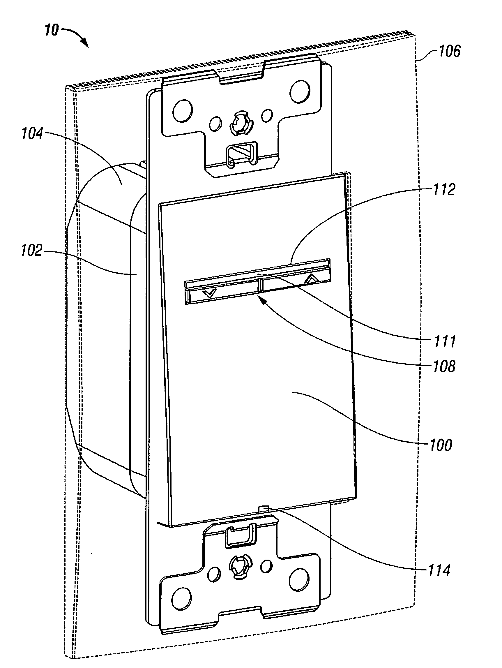
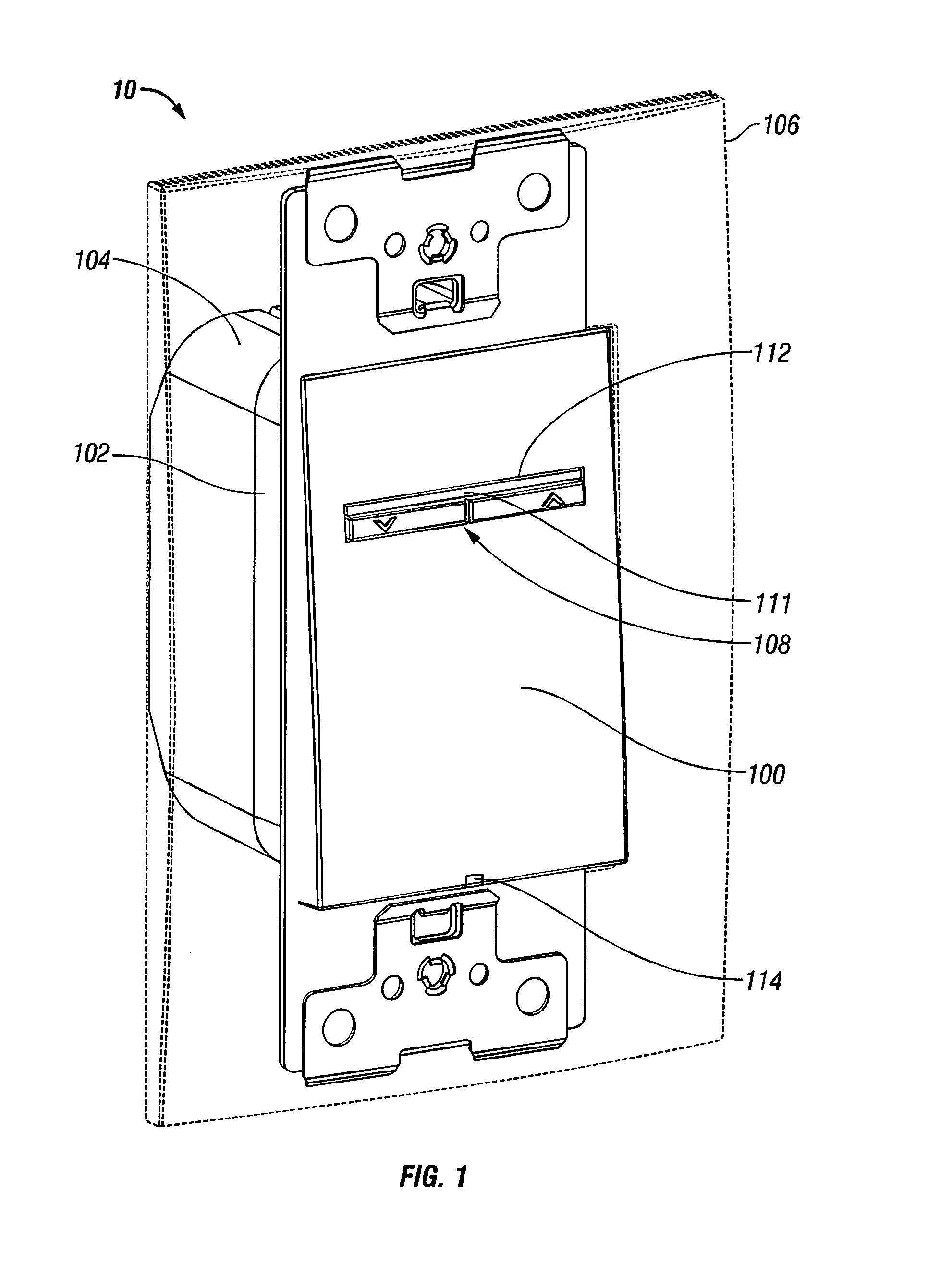
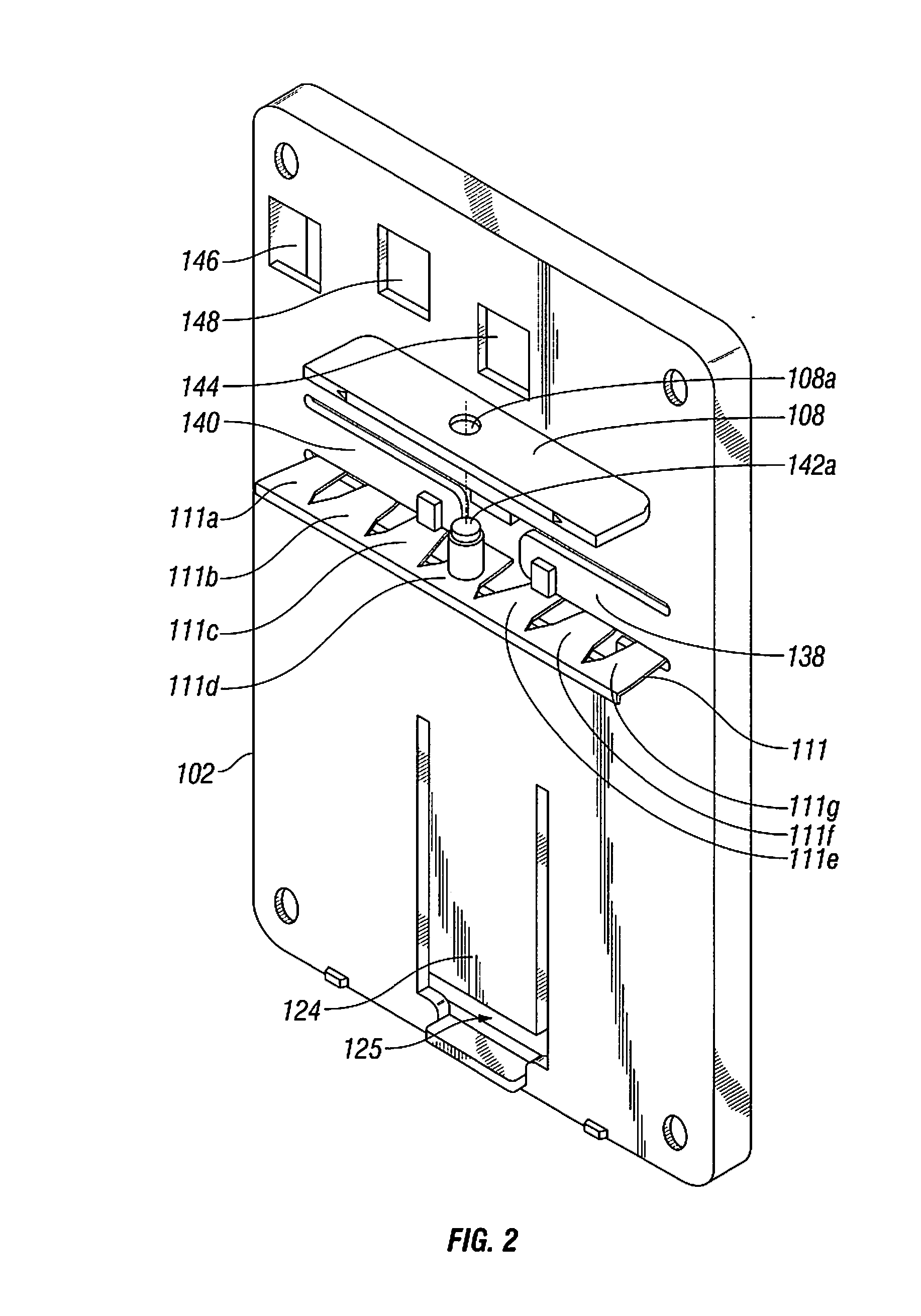
[0024]The switching device described herein in accordance with the present disclosure relates to a dimmer-like switch characterized by a large paddle actuator having an intensity actuator embedded therein. The paddle actuator is preferably substantially rectangular in shape having a pair of opposing long sides and top and bottom short sides. The paddle actuator is biased to a rest or neutral position by a one or more springs (e.g., leaf springs) formed in a sub-panel below the paddle. A user may press the paddle to overcome the bias and cause the paddle to rotate about one or more pivots to a depressed position wherein an ON / OFF swi...


PUM


Abstract

A switching device includes a housing and a paddle actuator operably coupled to a front face of the housing and adapted to control a state of a load. The paddle actuator has a pair of opposing long sides and short sides and is configured to pivot about a hinge disposed proximate to one of the short sides of the paddle actuator. At least one component is disposed adjacent to the short side of the paddle actuator that is disposed proximate to the hinge and is configured to sense at least one condition. A control element is configured to control at least one of a sensing range and a sensitivity of the at least one component. The paddle actuator occupies at least 50% of the front face of the housing and the at least one component substantially occupies the remainder of the front face.

Description

CROSS REFERENCE TO RELATED APPLICATIONS[0001]This application is a continuation-in-part of U.S. Patent Application entitled “DIMMER SWITCH” filed in the United States Patent and Trademark Office on Jul. 8, 2008 and assigned Ser. No. 12 / 169,233, which claims priority to Provisional Patent Application entitled “DIMMER SWITCH” filed in the United States Patent and Trademark Office on Jul. 18, 2007 and assigned Ser. No. 60 / 961,188, the entire contents of all of which being incorporated by reference herein.BACKGROUND[0002]1. Technical Field[0003]The present invention relates to a switching device used to control electrical systems and / or devices and, more particularly, relates to a switch for selectively adjusting or varying a state of a current load.[0004]2. Description of Related Art[0005]Switches and controls for electrical systems and devices have been developed that control more than one state of an electrical load or device. While it is now commonplace for devices to control a plur...

Claims


Application Information

Patent Timeline
Patent Type & Authority Applications(United States)
IPC IPC(8): H01H3/00
CPCH01H9/0271H01H23/26H01H23/025
Inventor WU, YUNLOMBARDI, ALFRED J.CHOU, CHENG-LUNGILKHANOV, AZER
Owner LEVITON MFG
Why Eureka
Try Eureka